- HELP
- Technical Information
- CNC Milling
- Design Guidelines
- Recognizing Different Types of Hole
Recognizing Different Types of Hole
Shape Elements Identified as Holes
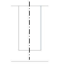
| Blind cylindrical shape with flat hole base |
 |
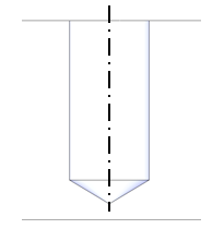
| Blind cylindrical shape with conical hole base |
 |
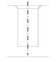
| Blind cylindrical shape with flat hole base +90° chamfer at entrance |
 |
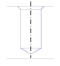
| Blind cylindrical shape with conical hole base +90° chamfer at entrance |
 |
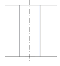
| Through cylinder |
 |
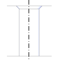
| Through cylinder +90° chamfer at entrance |
 |
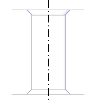
| Through cylinder +90° chamfer at entrance (both sides) |
 |
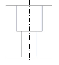
| One-step hole |
 |
Two-step hole |
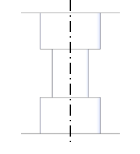 |
Recognizing Straight Holes
Any shape that is identified as a hole, but is not initially recognized to be a tapped hole or a countersunk hole, is identified as a straight hole.
Settings for Precision Holes
Recognizing Tapped Holes
meviy sets the pilot-hole diameter based on the user-set “Tapped Hole Identification Settings” and the file extension (see table below). If the model’s hole diameter matches the settings, it is identified as a tapped hole.
If holes have not been automatically assigned as tapped holes at initial upload, you can also change the hole type manually as long as the hole diameter is within the threshold.
You can also change from tapped holes to straight or insert holes.
See here for the Tapped Hole Identification Settings.
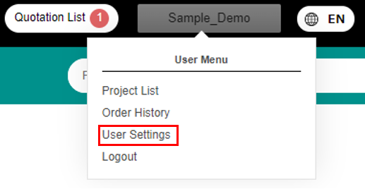
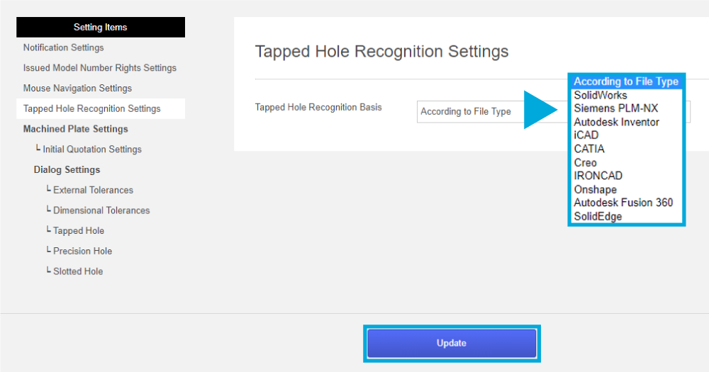
- Select “User Settings” in the user menu in the top-right of the screen.
- You can change the settings from the “Tapped Hole Identification Settings” menu.
- Once you have changed the settings, click “Change.”
For intermediate files: select the CAD program used to create the file
*In order to improve the accuracy of the automatic assignment of tapped holes, you should always try to select the original CAD program used to create the file.
Example: CATIA → SOLIDWORKS (upload) CAD Software Settings
✓ Select: CATIA
X Don’t select: SOLIDWORKS
*If the native file is different from the CAD software settings, the CAD software setting logic will be used for recognizing tapped holes.

It is recommended that you use the hole commands to model holes. The machining service is designed for modeling generated with the various CAD hole commands, and using the hole commands improves the accuracy of the automatic assignment of tapped holes.
(Automatic tapped-hole assignment can also be used when modeling with cutting. However, if there is any discrepancy in the logic, tapped holes cannot be automatically assigned, and holes may end up as straight holes or other types of hole.)
Please note (SOLIDWORKS users only)
The machining service refers to the CAD names in the SOLIDWORKS Tapped Hole Identification Settings as “SOLIDWORKS(A)” and “SOLIDWORKS(B).” The differences between the two are as shown below.
Select according to your modeling specifications.
If a user of modeling specification “SOLIDWORKS(B)” has set the CAD name to “Use file type” in the Tapped Hole Identification Settings, the “SOLIDWORKS(A)” logic will take precedence.
“SOLIDWORKS(B)” users must set the CAD name to “SOLIDWORKS(B).”
The tapped hole identification logic for the machining service is shown below.
*The machining service’s tapped hole identification logic is designed to round to three decimal places.
*The CAD in the following tables assumes the default versions of the following are used.
It may not work, depending on version upgrades and personal settings.
| Autodesk Inventor 2023 | Siemens PLM-NX 2206 |
| CATIA V5-R62022 | Solid Edge 2023 |
| Creo 9.0 | SOLIDWORKS 2023 |
| Pro/Engineer 19.0 | I-deas |
| Onshape 1.154.6978 | iCAD SX V8L3-00A |
| Autodesk Fusion 2.0.10813 | IRONCAD 2021 |
Automatic Tapped-Hole Assignment
Recommended Tapped Hole Identification Setting: CAD Software
| Model Hole Diameter | (1) Upload Model: Native/Intermediate File | |||||
|---|---|---|---|---|---|---|
| (ø) mm | (2) Tapped- Hole Identification Setting: CAD Name | |||||
| Tap Size (Coarse) | Creo Onshape SW(A) | Solid Edge IronCAD | NX | CATIA V5 Inventor | SW(B) iCAD SX | Autodesk Fusion |
| M2 | 1.6 | 1.6 | 1.57 | 2 | 1.62 | |
| M2.5 | 2.05 | 2.05 | 2.01 | 2.5 | 2.08 | |
| M3 | 2.5 | 2.5 | 2.46 | 3 | 2.53 | |
| M4 | 3.3 | 3.3 | 3.24 | 4 | 3.33 | |
| M5 | 4.2 | 4.2 | 4.13 | 5 | 4.23 | |
| M6 | 5 | 5 | 4.92 | 6 | 5.04 | |
| M8 | 6.8 | 6.8 | 6.65 | 8 | 6.78 | |
| M10 | 8.5 | 8.5 | 8.38 | 10 | 8.53 | |
| M12 | 10.2 | 10.3 | 10.11 | 12 | 10.27 | |
| M14 | 12 | 12.1 | 11.84 | 14 | 12.02 | |
| M16 | 14 | 14 | 13.84 | 16 | 14.02 | |
Not Recommended: Tapped- Hole Identification Setting "Use File Type"
| Model Hole Diameter | (1) Upload Model: Native File | ||||
|---|---|---|---|---|---|
| (ø) mm | (2) Tapped- Hole Identification Settings: Use File Type | ||||
| Tap Size (Coarse) | Creo Onshape SW(A) | Solid Edge IronCAD NX | CATIA V5 Inventor | SW(B) iCAD SX | Autodesk Fusion |
| M2 | 1.6 | 1.57 | 2 | 1.62 | |
| M2.5 | 2.05 | 2.01 | 2.5 | 2.08 | |
| M3 | 2.5 | 2.46 | 3 | 2.53 | |
| M4 | 3.3 | 3.24 | 4 | 3.33 | |
| M5 | 4.2 | 4.13 | 5 | 4.23 | |
| M6 | 5 | 4.92 | 6 | 5.04 | |
| M8 | 6.8 | 6.65 | 8 | 6.78 | |
| M10 | 8.5 | 8.38 | 10 | 8.53 | |
| M12 | 10.2 | 10.11 | 12 | 10.27 | |
| M14 | 12 | 11.84 | 14 | 12.02 | |
| M16 | 14 | 13.84 | 16 | 14.02 | |
| Model Hole Diameter | (1) Upload Model: Native File | ||||
|---|---|---|---|---|---|
| (ø) mm | (2) Tapped- Hole Identification Settings: Use File Type | ||||
| Tap Size (Coarse) | STEP Parasolid ACIS JT PRC I-DEAS | ||||
| M2 | 1.57/1.6/1.62/2 | ||||
| M2.5 | 2.01/2.05/2.08 | ||||
| M3 | 2.46/2.5/2.53/3 | ||||
| M4 | 3.24/3.3/3.33/4 | ||||
| M5 | 4.13/4.2/4.23 | ||||
| M6 | 4.92/5/5.04/6 | ||||
| M8 | 6.65/6.75/6.78/6.8/8 | ||||
| M10 | 8.38/8.5/8.53/10 | ||||
| M12 | 10.11/10.2/10.25/10.27/10.3 | ||||
| M14 | 11.84/12/12.02/12.1 | ||||
| M16 | 13.84/14/14.02/16 | ||||
Tapped-Hole Manual Assignment
| Tap Size(Coarse/Fine) | Model hole diameter (ø) mm | ||||
|---|---|---|---|---|---|
| M2 | 1.5 to 2 | ||||
| M2.5 | 2 to 2.5 | ||||
| M3 | 2.4 to 3 | ||||
| M4 | 3.2 to 4 | ||||
| M5 | 4.1 to 5 | ||||
| M6 | 4.9 to 6 | ||||
| M8 | 6.6 to 8 | ||||
| M10 | 8.3 to 10 | ||||
| M12 | 10.1 to 12 | ||||
| M14 | 11.8 to 14 | ||||
| M16 | 13.8 to 16 | ||||
*SW(A) when created with the SOLIDWORKS hole specification options “Screw pilot-hole drill diameter” and “Thread”
*SW(B) when created with the SOLIDWORKS hole specification option “Remove thread”
Settings for Insert Holes
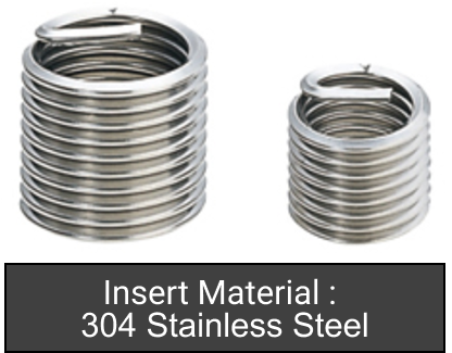
When the quoted material is made of aluminum or resin, the machining service can select insert holes within the threshold using logic equivalent to the tapped-hole identification logic.
The insert material is 304 Stainless Steel
There are four nominal lengths for each diameter: 0.5D, 1D, 1.5D and 2D.
However, the number of selectable diameters is M2 to M12, unlike for tapped holes.
Recognizing Countersunk Holes
 |
 |
Conical shapes that meet the following conditions will be identified as countersunk holes.
Model the conical shape with an angle of 90°.
Set so that the hole diameter ratio D/d is:
greater than 1.4 (D>1.4d) when d is 4.0 [mm] or less.
greater than 1.7 (D>1.7d) when d is greater than 4.0 [mm].
Recognizing Other Types of Hole
The shapes shown below are recognized as other types of hole. The service is not available if these other types of hole are present.
| Decreasing two-step hole |
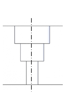 |
| Non-90° entrance chamfer |
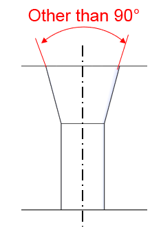 |
| Tapered hole |
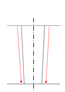 |
| Oblique hole |
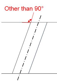 |
| Fillet at entrance |
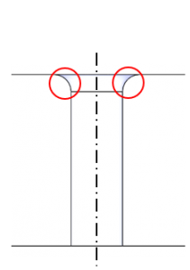 |
| Machined thread |
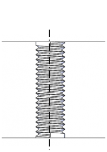 |
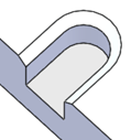
Recognizing Slotted Holes
The following shape elements are recognized as slotted holes. Shape elements recognized as slotted holes can be changed to precision holes using the dialog box. You can also specify the dimensional tolerance from the arc center.
| Through-hole shape with width = 2R |
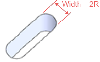 |
Through-hole shape with width = 2R, |
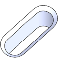 |
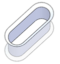
| Through-hole shape with width = 2R, +90° chamfer at entrance (both sides) |
 |
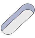
| Blind hole with width = 2R |
 |
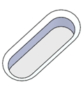
| Blind hole with width = 2R, +90° chamfer at entrance |
 |
| +90° U-shaped through slot where width = 2R |
 |
| U-shaped through slot with width = 2R, with 90° chamfer at entrance (one side) |
 |
| U-shaped through slot with width = 2R, +90° chamfer at entrance (both sides) |
 |
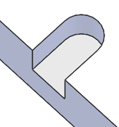
| U-shaped blind slot with width = 2R |
 |
| U-shaped blind slot with width = 2R +90° chamfer at entrance |
 |