- HELP
- How to use
- Quotation conditions settings
- [CNC Milling] Quotation Settings
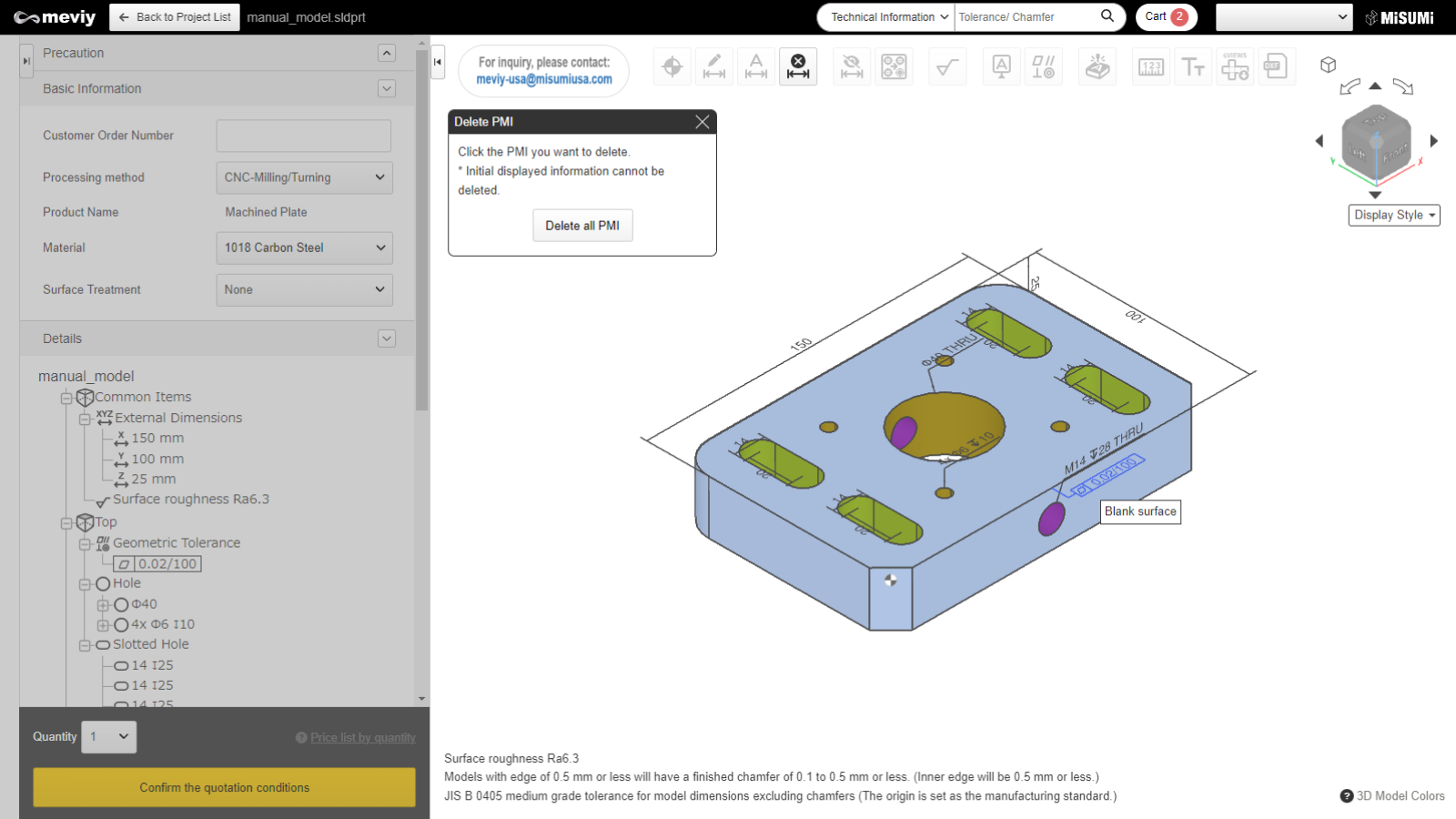
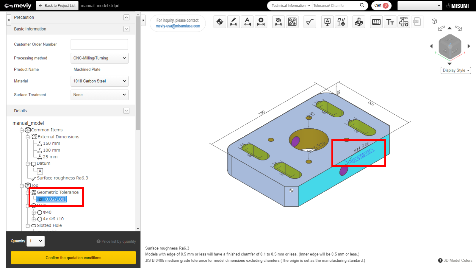
- Set datum and geometric tolerances
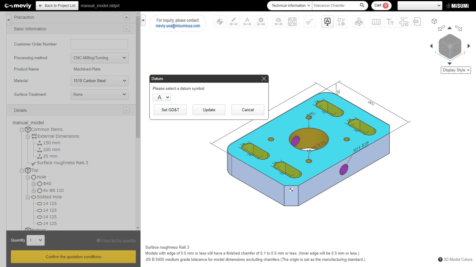
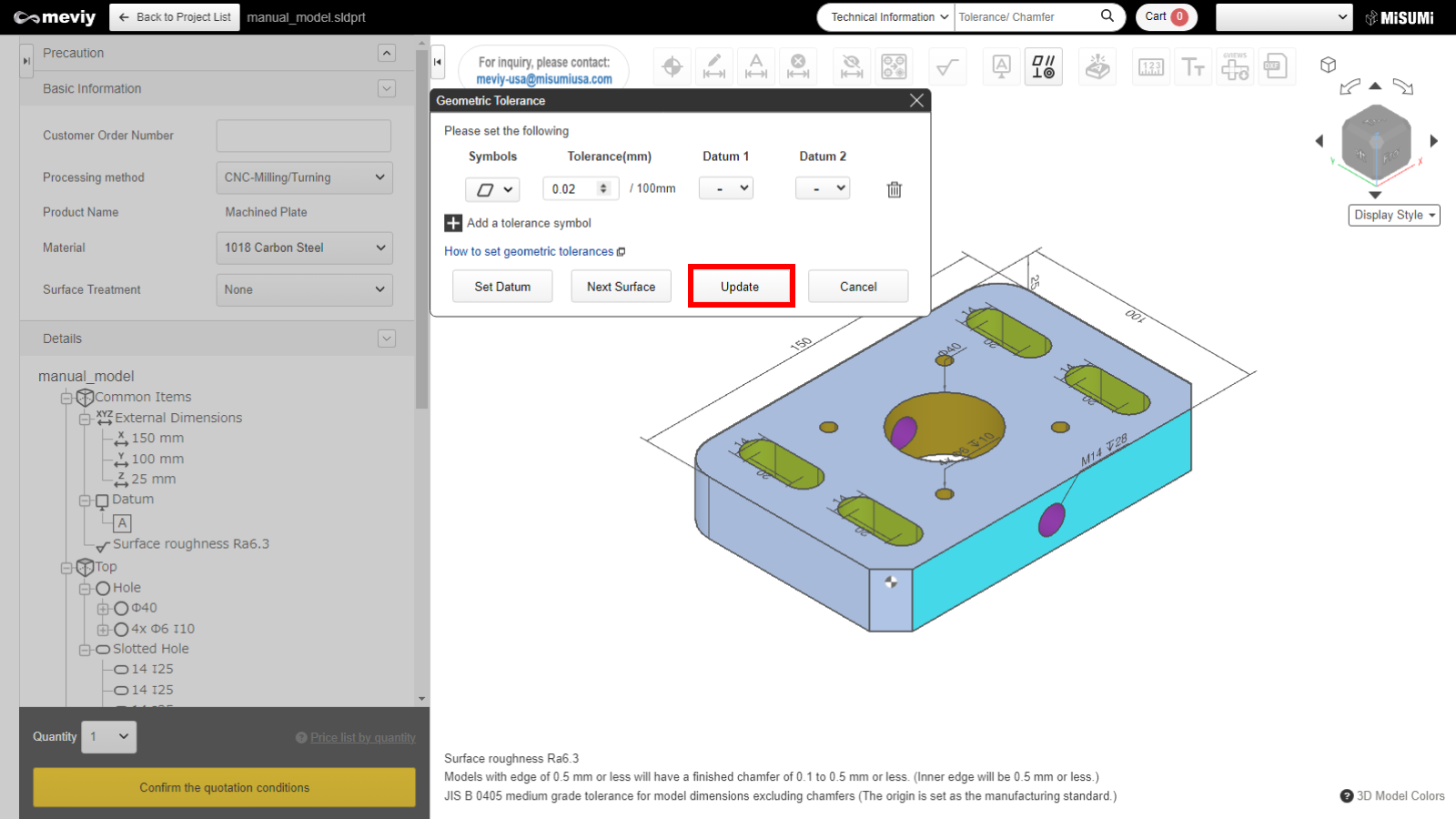
Set datum and geometric tolerances
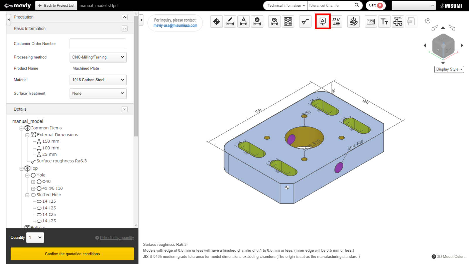
Select  from the icons at the top.
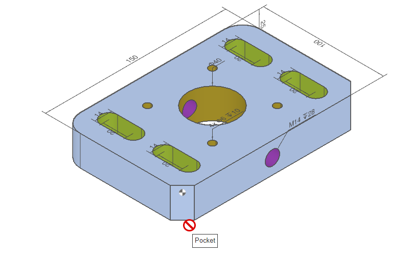
Caution
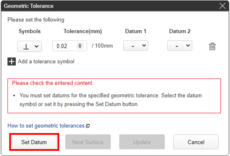
- In the following cases, the datum cannot be set and the button cannot be clicked.
- – The parts have a pocket(s) (excluding C-chamfer and fillet surfaces)
- – Any of the external dimensions is less than 10 mm
- – Any of the external dimensions is more than 300 mm
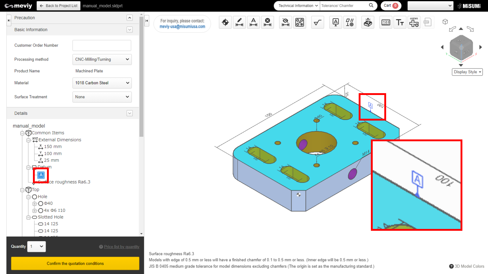
- Datum settings are not available for shapes, such as those containing pocket shapes within the part.
- If the surface is not selectable, the “Not Selectable” icon will be displayed when the mouse hovers over it.
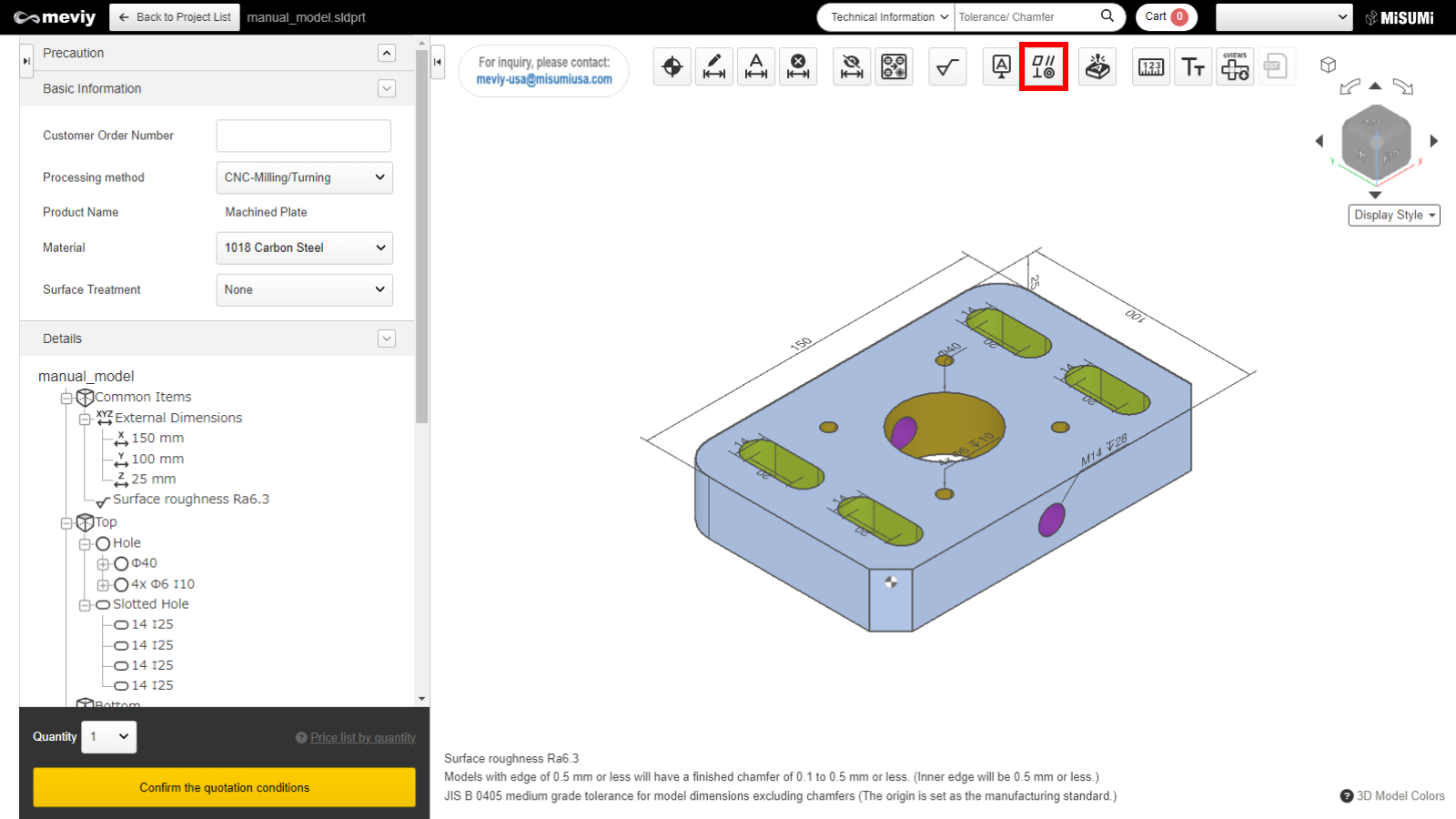
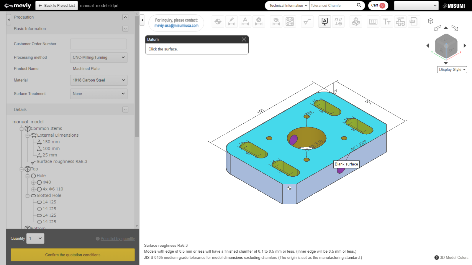
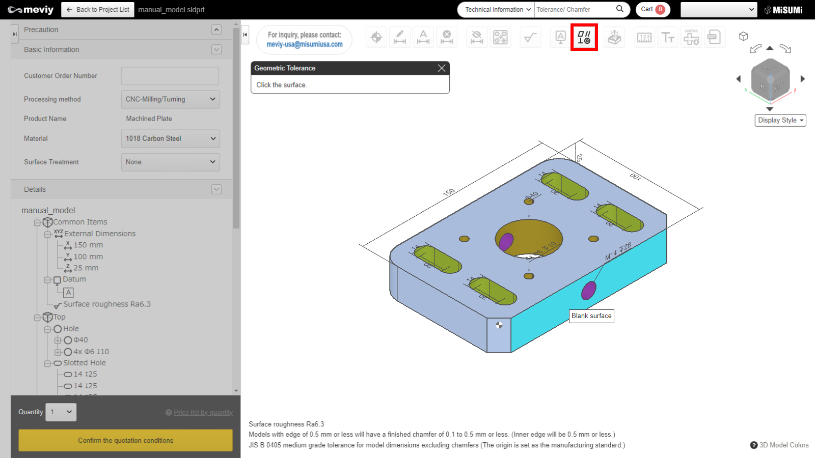
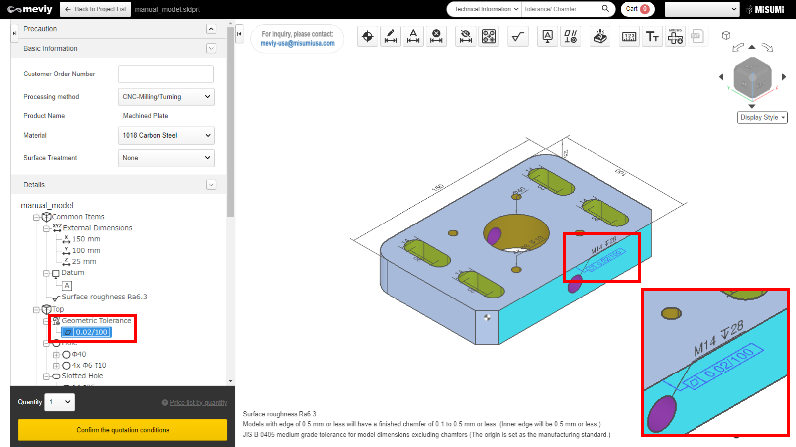
Select  from the icons at the top. It can also use the shortcut key (G) to select it.
Caution
- If the surface is not selectable, the “Not Selectable” icon will be displayed when the mouse hovers over it.
Tip
- Even if the datum settings have not been completed, you can specify another datum by clicking the “Datum Settings” button at the bottom left.
- *The settings up to this step will be temporarily saved.
| geometric tolerance | Icon | Tolerance range |
|---|---|---|
| Parallelism | 0.02~0.99 | |
| Flatness | 0.02~0.99 | |
| Squareness | 0.02~0.99 |
Tip
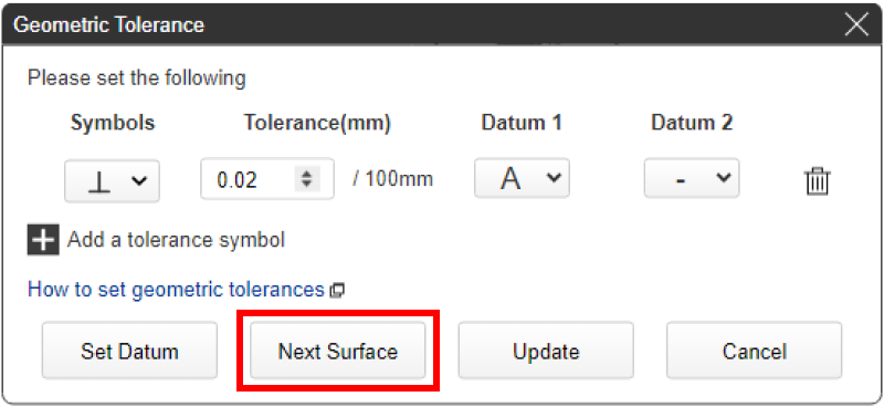
- If you press the “Select next surface” button without pressing Update, you can set a new geometric tolerance on another surface.
- *The settings up to this step will be temporarily saved.
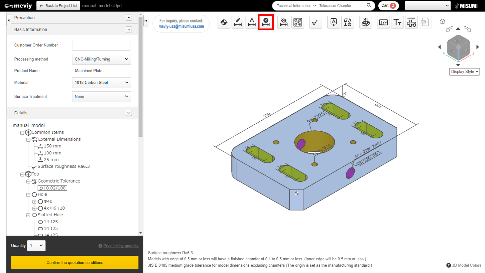
Select  from the icons at the top.