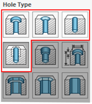
| Straight Hole & Through Hole |
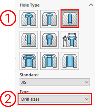 |
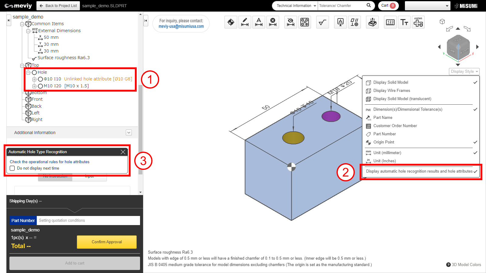
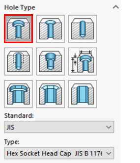
- 1) Select “Hole”
- 2) Selectable Type
- – Drill sizes
- – Screw Clearances
- – Tap Drills
|
When Dowel Holes are selected, they are linked as “precision holes,” so do not select Dowel Holes if you want to recognize them as straight or through holes. |
| Straight Hole
(Counterbored hole)
*CNC Milling only |
 |
Select “Counterbore” |
|
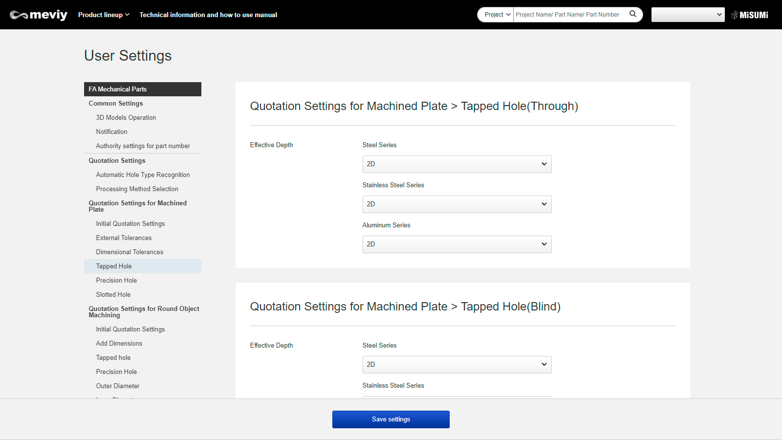
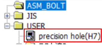
| Precision Hole
*CNC Milling only |
 |
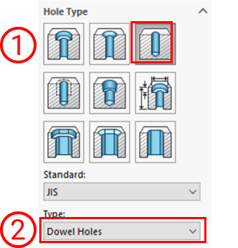
- 1) Select “Hole”
- 2) Select “Dowel Holes”
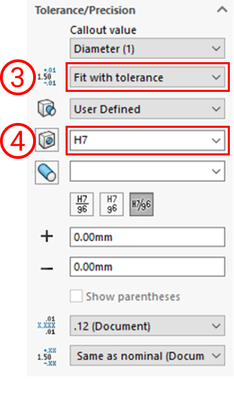
- 3) Select “Fit with tolerance”
- 4) Set “Hole Fit”
|
- – Effective depth can be set in user setting.
- – The hole diameter refers from the diameter of the 3D CAD file and the tolerance range class refers to the setting of the hole command. If fit tolerance is not set, it refers to the tolerance range class used in the user settings.
- – As tolerance on both side(e.g. ±0.02) and tolerance on one side (e.g. +0.02/0) cannot be linked, please make sure to confirm and set on 3D Viewer.
- The initial display refers to the tolerance range class that is set in the user settings.
|
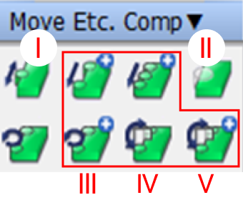
| Tapped hole & Friction drilled/tapped holes |
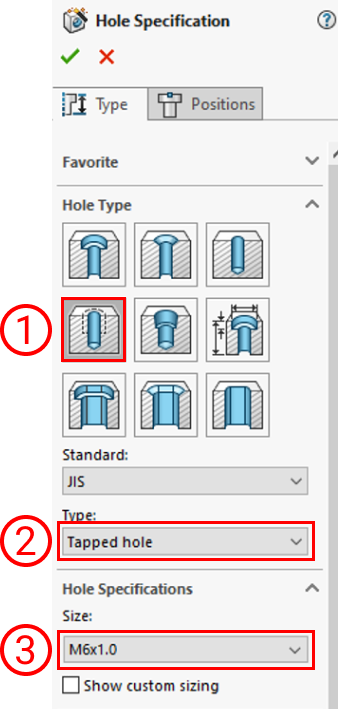 |
- 1) Select “Straight Tap”
- 2) Select “Tapped hole”
- 3) Select size (M)
|
- – Holes will be recognized as coarse thread when pitch size could not be acquire.
- – Effective depth will be set by the dialog set information in user setting is applied.
- – Shapes and sizes would follow the meviy’s friction drilled/tapped holes rules.
- Click here for friction drilled/tapped holes rules.
|
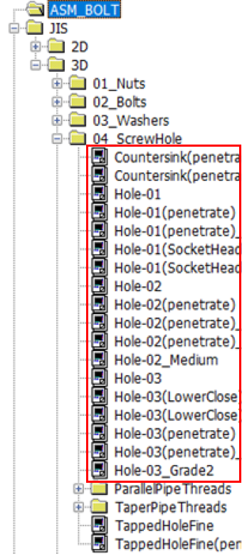
| Countersunk hole |
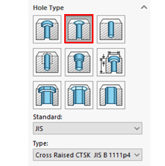 |
|
|
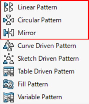
| Non linkage hole e.g.1 |
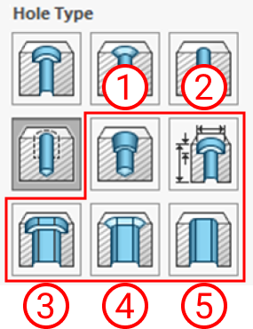 |
- Holes using the following hole commands (hole wizard) are not eligible to linkage.
- 1) Tapered Tap
- 2) Legacy Hole
- 3) Counterbore Slot
- 4) Countersink Slot
- 5) Slot
|
|
| Non linkage hole e.g.2 |
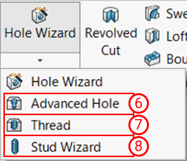 |
- Holes using the following hole commands (hole wizard) are not eligible to linkage.
- 6) Advanced hole
- 7) Thread
- 8) Stud Wizard
- Holes using other than hole commands (hole wizard), such as Extruded Cut or Revolved Cut are not applicable to linkage.
|
If it is made with these hole commands, the message “Hole command not used” will be displayed. |