Dimensional tolerances that can be specified

  • When the 3D CAD data is uploaded, You can specify dimensional tolerances for areas where dimensions and tolerances are not displayed
  • The minimum tolerance (range) that can be specified varies for each combination of geometry elements.

Fit Tolerance

The fit tolerances that can be set for lathe machining and secondary machining are as follows.
Type of Machining Fit Tolerance
Lathe Metal: Grade IT6 or above
  • MC
  • (Secondary Machining)
Metal:Grade IT7 or above

Dimensional Tolerances for Full Length (L) and Length (ℓ)

The tolerances that can be set for the full length and the length of each element (part) are as follows.
[mm]
Metal Full Length (L) and Length (ℓ)
Example of Minimum Tolerance Range
L,ℓ ≦ 200 * ±0.02 0.04
200 < L, ℓ ≦ 500 ±0.05 0.1
500 < L, ℓ ±0.2 0.4
*The range that can be set will change for the following thin plates.
Metal Full Length (L) and Length (ℓ)
Example of Minimum Tolerance Range
L ≦ 5 150<D ±0.1 0.2
L<10 50 ≦ D
Resin Full Length (L) and Length (ℓ)​
Example of Minimum Tolerance​ Range​
L,ℓ ≦ 100​ ±0.05 0.1​
100< L,ℓ ≦ 200​ ±0.1​ 0.2
200< L,ℓ ≦ 300 ±0.2 0.4
25537_01_usEN
25537_02_usEN
25537_03_usEN

Tolerances for Groove Outer Diameter (D), Groove Width (w) and Location Dimensions (ℓ)

The tolerances that can be set for the outer diameter are as follows.
[mm]
Tolerances for Groove Inner Diameter (d) Minimum Tolerance Range​
±0.05​ 0.1
Groove Width(w) Minimum Tolerance Range​
±0.07 0.14​
Location Dimensions(ℓ) Minimum Tolerance Range​
±0.1​ 0.2​
25537_04_usEN

*Tolerance between inner and outer diameter surfaces cannot be added.

Tolerances for Groove Inner Diameter (d), Groove Width (w) and Location Dimensions (ℓ)

The tolerances that can be set for the inner diameter are as follows.
[mm]
Tolerances for Groove Inner Diameter (d) Minimum Tolerance Range​
±0.05​ 0.1
Groove Width(w) Minimum Tolerance Range​
±0.07 0.14​
Location Dimensions(ℓ) Minimum Tolerance Range​
±0.1​ 0.2​
25537_05_usEN
  • *Tolerances cannot be added to the inner diameter groove and other elements.
  • However, the positional dimension from the end face of the ℓ section is excluded.

Tolerances for Each Part

The tolerances that can be set between each shape element are as follows.
25537_06_usEN
25537_07_usEN

[mm]

No Shape Element (2) Outer Diameter Side (3) External Groove Side (4) Pocket Surface (5) Inner Diameter Bottom (6) Internal Groove Side
(1) Both End Faces 0.04~ 0.1~ 0.1~ 0.04~ 0.2~
(2) Outer Diameter Side
(3) External Groove Side 0.2~
(4) Pocket Surface 0.1~
(5) Inner Diameter Bottom 0.04~
(6) Internal Groove Side 0.2~
25537_08_usEN

[mm]

No Shape Element (5) Precision Hole Center (6) Straight Hole Center (7) Tapped Hole Center (8) Insert hole center (9) Countersink center (10) Slotted Hole/Keyway
(1) Both End Faces/Central Axis 0.1~ 0.2~ 0.2~ 0.2~ 0.2~ 0.2~
(2) Outer Diameter Side
(3)
External Groove Side
0.2~
(4)
Pocket Surface
0.1~
(5)
Precision Hole Center
(6)
Straight Hole Center
(7)
Tapped Hole Center
(8)
Insert hole center
(9)
Countersink center
(10)
Slotted Hole/Keyway

Tip

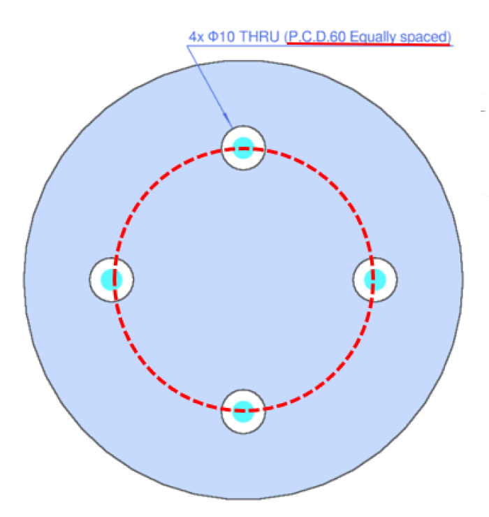
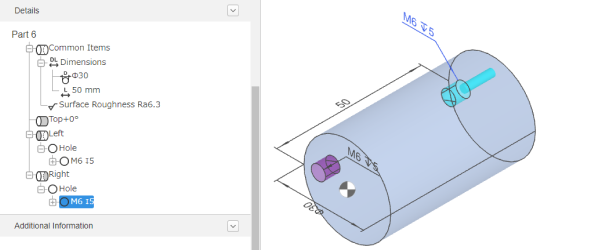
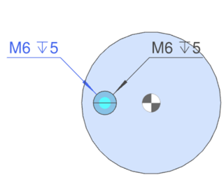
  • (1) Holes on the same circumference are called P.C.D. (Pitch Circle Diameter). Cross bores are not supported.
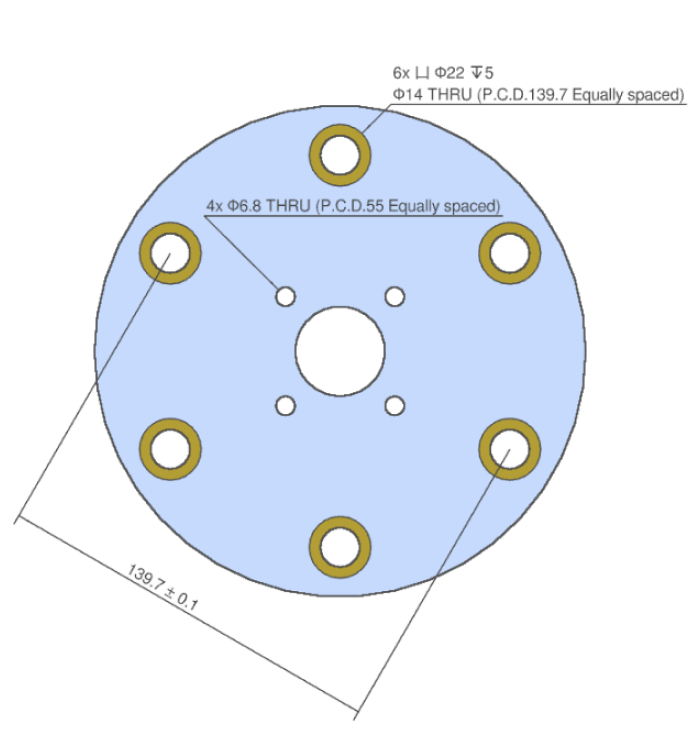
  • (2) P.C.D is recognized even with different hole types.
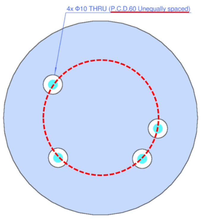
  • (3) P.C.D. is recognised regardless of whether the positions of the holes are equally or unequally divided.
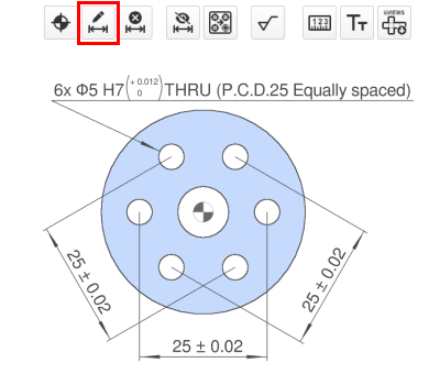
  • (4) It is possible to add diagonal dimensions that specify the distance between P.C.D. holes.
  • How to use > Adding/Deleting Dimensions and Dimensional Tolerances
P.C.D. Equally divided P.C.D. Unequally divided The distance between P.C.D. holes.

Caution

  • P.C.D. recognition is supplementary and reference information in meviy for Turning Parts.
  • If you need to specify the tolerance between holes, please select the “Add tolerance” icon and specify the tolerance for the target position.

Tip

  • The positional relationship of holes on both end faces of the reference model in the figure below is a general tolerance. Positional tolerances cannot be specified for topologically related shapes..

Notes

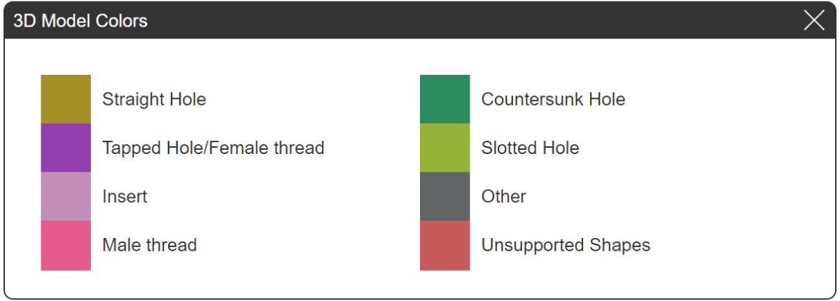
  • 3D Model Colour Schemes
  • If a colour scheme for an unsupported shape is displayed, automatic quotation is not available.