- HELP
- How to use
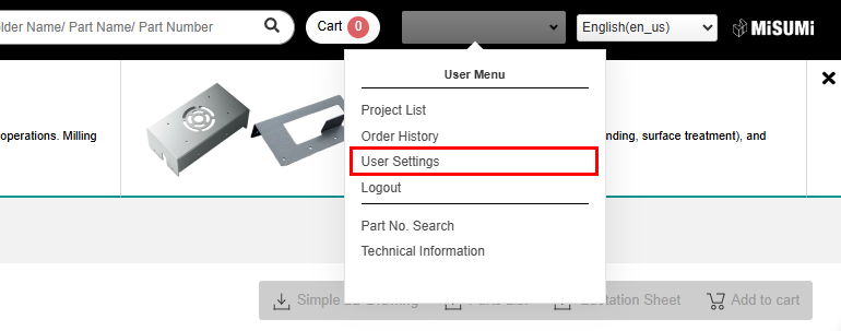
- Before You Begin
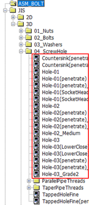
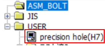
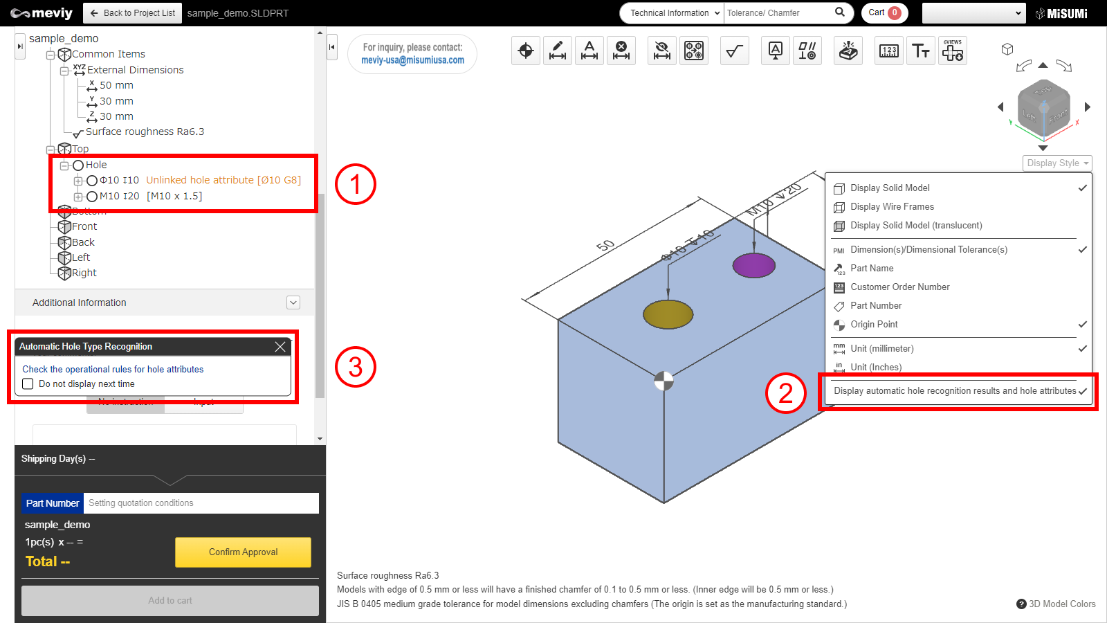
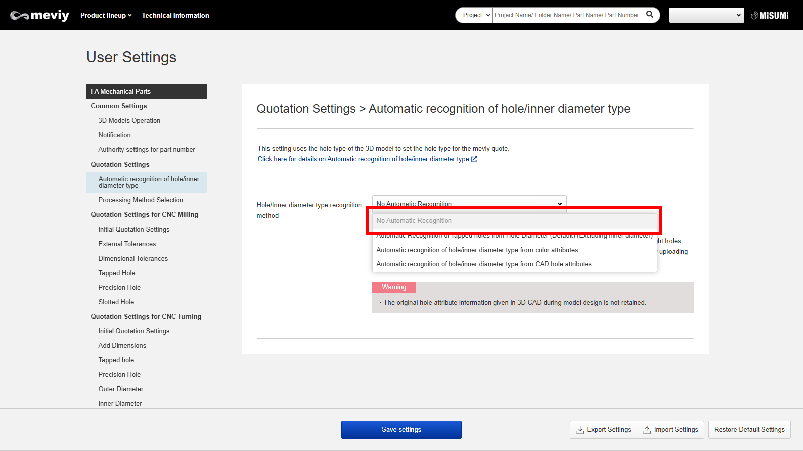
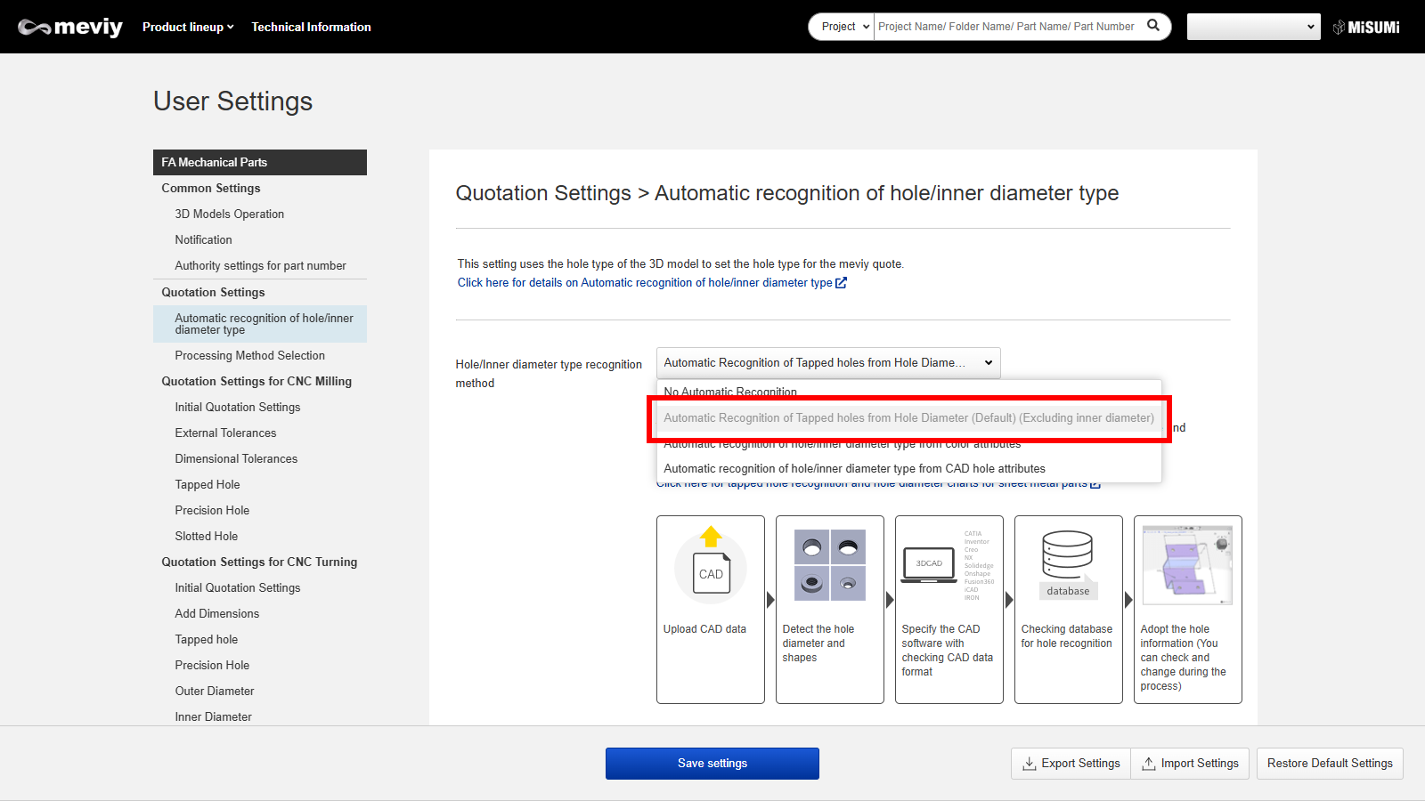
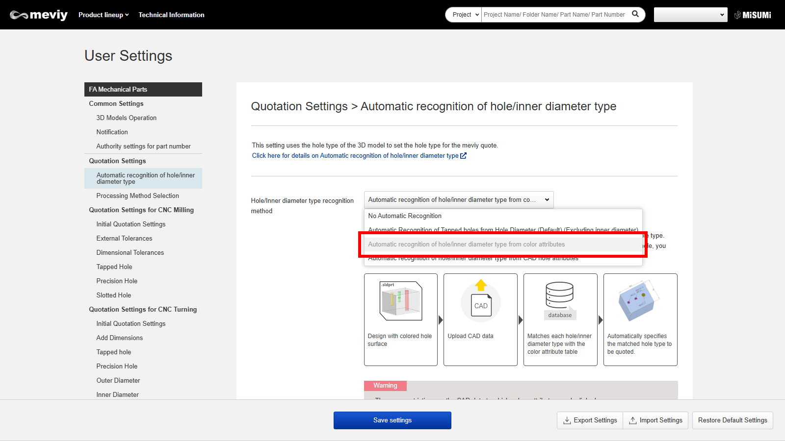
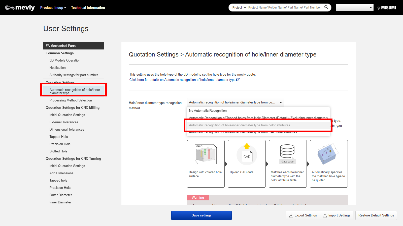
- Automatic hole/inner diameter type Recognition
Automatic hole/inner diameter type Recognition
| SOLIDWORKS | iCAD SX |
|---|
| (2) | 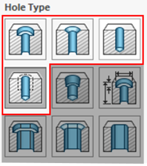 |
|
|---|---|---|
| (4) |  |
|
| (5) |  |
|