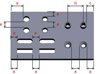
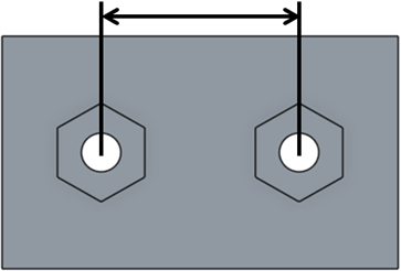
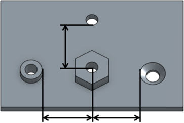
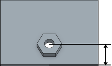
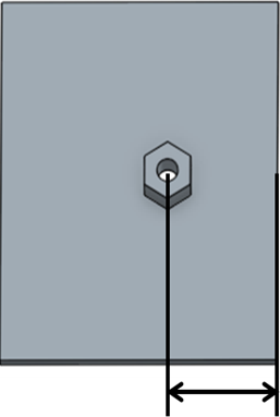
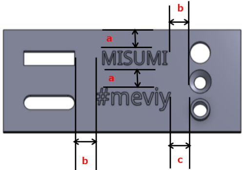
Machining Limits, Size Range
| Material | Sheet thickness(Gauge) | Thickness (Inch) | Limit a | Limit b | Limit c |
|---|
|
26 | 0.0179″ | 1.0 | Friction drilled tapped hole is not available in Inch gauge sheetmetal | |
|---|---|---|---|---|---|
| 24 | 0.0239″ | 1.0 | |||
| 22 | 0.0299″ | 0.5 | |||
| 20 | 0.0359″ | 0.5 | |||
| 19 | 0.0418″ | 0.5 | |||
| 18 | 0.0478″ | 1.0 | |||
| 17 | 0.0538″ | 1.0 | |||
| 16 | 0.0598″ | 1.0 | |||
| 14 | 0.0747″ | 1.0 | |||
| 13 | 0.0897″ | 1.0 | |||
| 12 | 0.1046″ | 1.5 | |||
| 11 | 0.1196″ | 1.5 | |||
| 10 | 0.1345″ | 2.0 | |||
| 9 | 0.1495″ | 2.0 | |||
| 8 | 0.1644″ | 2.0 | |||
| 7 | 0.1793″ | 2.0 | |||
| 6 | 0.1943″ | 2.0 | |||
| (3/16) | 0.1875″ | 2.5 | |||
| (1/4) | 0.2500″ | 2.5 | |||
| (3/8) | 0.3750″ | 4.0 | |||
| (1/2) | 0.5000″ | 6.0 | |||
|
26 | 0.0217″ | 1.0 | ||
| 24 | 0.0276″ | 0.5 | |||
| 22 | 0.0336″ | 0.5 | |||
| 20 | 0.0396″ | 0.5 | |||
| 18 | 0.0516″ | 1.0 | |||
| 16 | 0.0635″ | 1.0 | |||
| 14 | 0.0785″ | 1.0 | |||
| 13 | 0.0934″ | 1.0 | |||
| 12 | 0.1084″ | 1.5 | |||
| 11 | 0.1233″ | 1.5 | |||
| 10 | 0.1382″ | 2.0 | |||
| 8 | 0.168″ | 2.0 | |||
| 7 | 0.1793″ | 2.0 | |||
|
26 | 0.0187″ | 1.0 | ||
| 24 | 0.0250″ | 1.0 | |||
| 22 | 0.0312″ | 0.5 | |||
| 20 | 0.0375″ | 0.5 | |||
| 19 | 0.0437″ | 0.5 | |||
| 18 | 0.0500″ | 1.0 | |||
| 17 | 0.0562″ | 1.0 | |||
| 16 | 0.0625″ | 1.0 | |||
| 14 | 0.0781″ | 1.0 | |||
| 13 | 0.0937″ | 1.0 | |||
| 12 | 0.1094″ | 1.5 | |||
| 11 | 0.1250″ | 1.5 | |||
| 10 | 0.1406″ | 2.0 | |||
| 8 | 0.1719″ | 2.0 | |||
| 7 | 0.1875″ | 2.0 | |||
| 3 | 0.2500″ | 2.5 | |||
|
26 | 0.0187″ | 1.0 | ||
| 24 | 0.0250″ | 1.0 | |||
| 22 | 0.0312″ | 1.0 | |||
| 20 | 0.0375″ | 1.0 | |||
| 18 | 0.0500″ | 1.0 | |||
| 16 | 0.0625″ | 1.0 | |||
| 14 | 0.0781″ | 1.0 | |||
| 12 | 0.1094″ | 1.5 | |||
| 11 | 0.1250″ | 1.5 | |||
| 10 | 0.1406″ | 2.0 | |||
| 7 | 0.1875″ | 2.0 | |||
| 1/4 | 0.2500″ | 3.0 | |||
| 1/2 | 0.5000″ | 6.0 | |||
|
– | 0.0200″ | 0.5 | ||
| – | 0.0250″ | 0.5 | |||
| – | 0.0320″ | 0.5 | |||
| – | 0.0400″ | 0.5 | |||
| – | 0.0500″ | 1.0 | |||
| – | 0.0630″ | 1.0 | |||
| – | 0.0800″ | 1.0 | |||
| – | 0.0900″ | 1.0 | |||
| – | 0.1000″ | 1.0 | |||
| – | 0.1250″ | 1.5 | |||
| – | 0.1600″ | 2.0 | |||
| – | 0.1900″ | 2.0 | |||
| – | 0.2500″ | 3.0 | |||
| – | 0.3125″ | 4.0 | |||
| – | 0.375″ | 4.0 | |||
| – | 0.5′ | 6.0 | |||
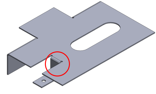
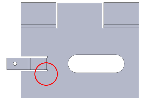
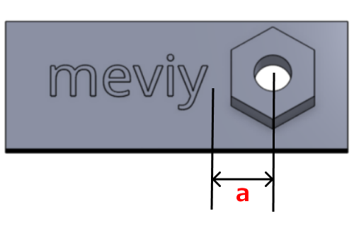
Example