The manufacturing process takes the 3D CAD data to be exact.
Do not forget to model the following shape elements.
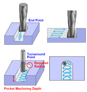
Radius (R) Required for End-Mill Trajectory End Point/Turnaround Point.
The end-mill trajectory will always have an R at the end point and the turnaround point.
Please model an R of at least 0.75 based on end-mill diameter and blade length.
The R required for an automatic estimate depends on the depth of the pocket machining.
The larger the R, the larger the diameter of the end mill that can be used. This means a shorter machining time and a lower cost.
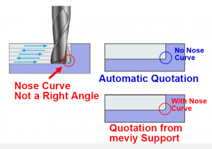
No Modeling Required for End-Mill Nose R
Do not model nose R.(The nose R is the minuscule R at the corner of the end-mill tip.)
If a nose R is present, the machining direction cannot be accurately determined, and an automatic estimate is not possible.
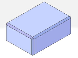
Chamfers Over C0.5 Must be Modeled
Chamfers greater than C0.5 must be modeled.
For external sharp corners or corners of C0.5 and smaller, this finish will be C0.1 to 0.5 or less.
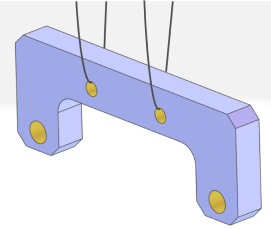
Hanging Holes for Surface Treatment Must Be Modeled
For trivalent chromate, Hard Chrome Plating, all anodized aluminum, and passivation, the part requires holes from which it can be hung and immersed in the treatment material.
Model the hanging holes with a combination of two or more of the following shapes. You can use any of the shapes multiple times in the same combination.
• Through holes of ø3.5 or greater (precision holes cannot be used)
• Slotted holes with a width of 3.5 or greater (precision slotted holes cannot be used)