- HELP
- Technical Information
- CNC Turning
- Accuracy and Machining Specifications
- Specifications for Male Thread, Female Thread, Keyways, Holes and Pockets
Specifications for Male Thread, Female Thread, Keyways, Holes and Pockets
Tip
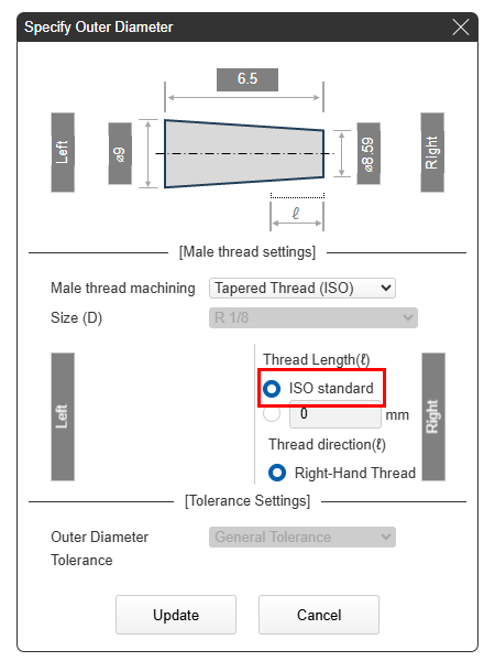
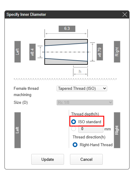
Thread length is automatically quoted using ISO standard lengths. Tapered pipe threads must pass a gauge inspection before the product is shipped.
Please request a Manual Quotation if a length other than the standard is required.
Caution
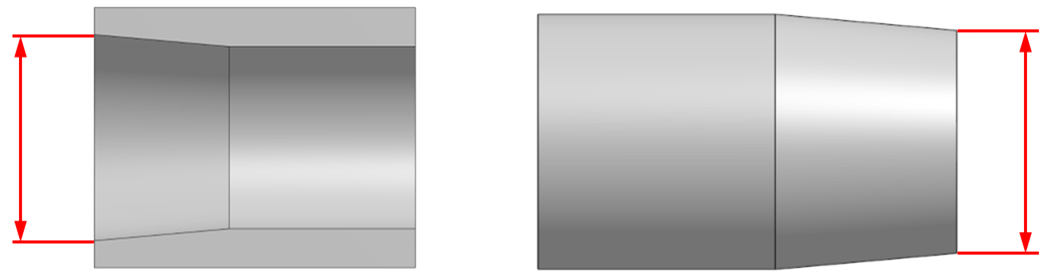
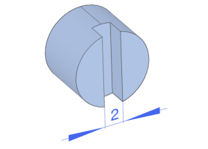
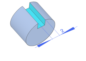
Model the taper into the part. The angle for tapered pipe threads can be specified between 0° and 2.5° with respect to the center axis.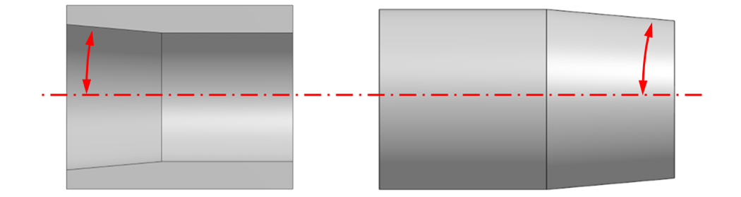
Caution
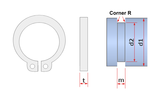
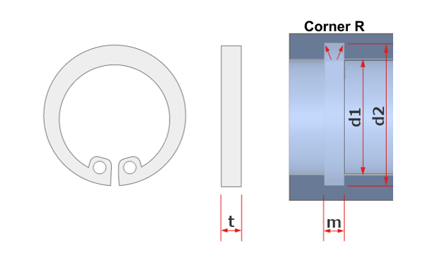
The diameter of the taper in the model is determined as shown in the figure below for Male and Female Threads. The diameter sizes recognized by meviy follow ISO standards.
(Reference) Tapered Pipe Threads (Excerpt from JIS B 0203:1999)