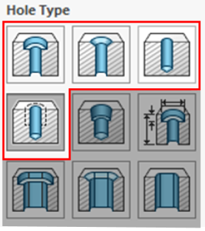
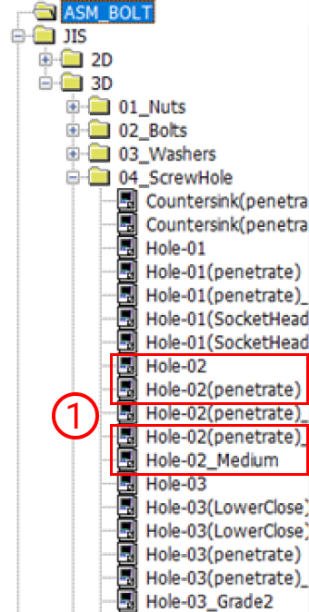
| Straight Hole/Through Hole |
|
- 1) Select one of the following
- – Hole-02
- – Hole-02 (penetrate)
- – Hole-02 (penetrate)_Medium
- – Hole-02_Medium
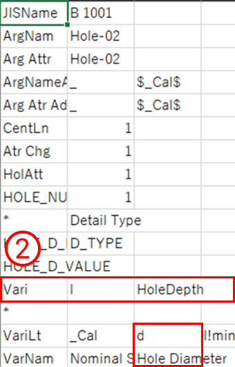
- 2) If you use user-defined, set the variable as follows
- – l,d
|
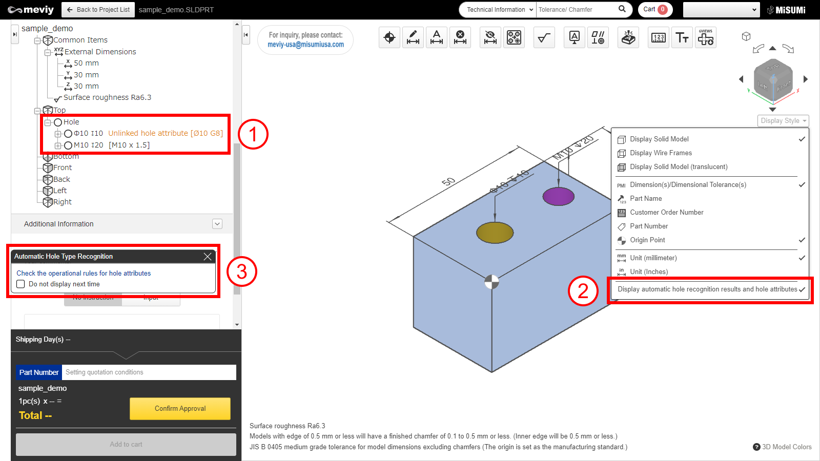
- If you set a value other than the variable specified in the user definition, it will not be linked.
- If either method (1) or (2) is used, it will be linked.
- If there is no special reason, we recommend using (1).
|
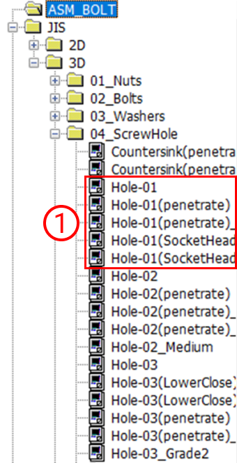
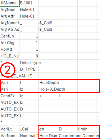
| Straight hole
(Counterbored hole)
*CNC milling only |
|
- 1) Select one of the following
- – Hole-01
- – Hole-01 (penetrate)
- – Hole-01 (penetrate)_Medium
- – Hole-01 (SocketHeadCapScrews)
- – Hole-01 (SocketHeadCapScrews)_Medium
- 2) If you use uer-defined, set the variables as follows
- – l,lz,dn,D
|
|
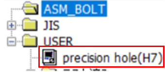
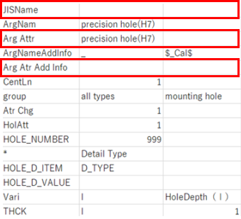
| Precision Hole
*CNC milling only |
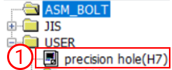 |
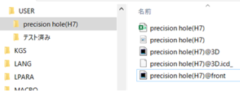
- 1) Select a hole created by user-defined.
- Please refer to the section below on how to create user-defined holes.
|
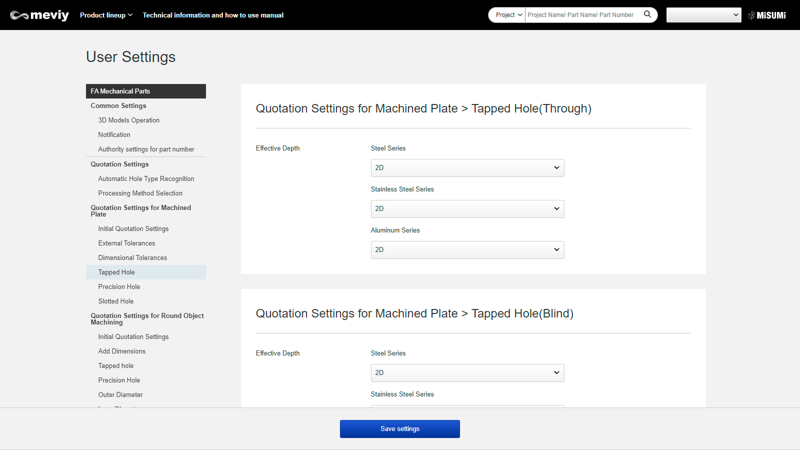
- – Effective depth can be set in user setting.
- – The hole diameter refers from the diameter of the 3D CAD file and the tolerance range class refers to the setting of the hole command. If fit tolerance is not set, it refers to the tolerance range class used in the user settings.
- – As tolerance on both side(e.g. ±0.02) and tolerance on one side (e.g. +0.02/0) cannot be linked, please make sure to confirm and set on 3D Viewer. The initial display refers to the tolerance range class that is set in the user settings.
|
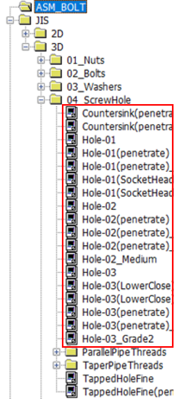
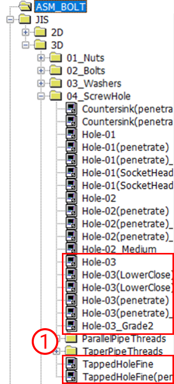
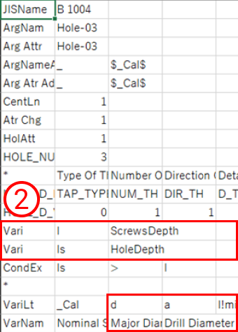
| Tapped hole & Friction drilled/tapped holes |
|
- 1) Select one of the following
- – Hole-03
- – Hole-03 (LowerClose)
- – Hole-03 (LowerClose)_Grade2
- – Hole-03 (penetrate)
- – Hole-03 (penetrate)_Grade2
- – Hole-03_Grade3
- 2) If you use user-defined, set the variable as follows
- – l,d,a
- – l,lr,d,a,ls
- – l,ls,d,a
- – l,lr,d,a
|
- If the pitch size cannot be obtained, it is recognized as a coarse thread.
- The effective depth applies to the information set in the User-defined hole dialog.
- Shape and size are based on the burring tapping rules of meviy.
- Click here for the barring tap rules for sheet metal.
- 1) and 2) can be linked by using either one of them.
In the absence of any special reason, we recommend using 1).
- When using 2), be sure to enter the nominal diameter in the “Nominal” field.
- In this case, if M is not attached, it will not be recognized as a nominal diameter.
|
| Countersunk hole |
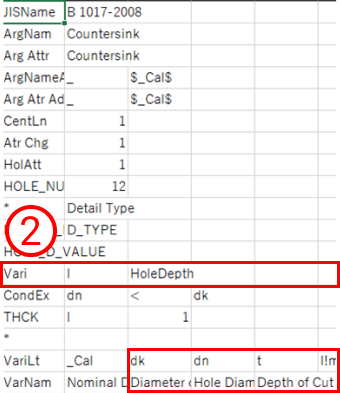 |
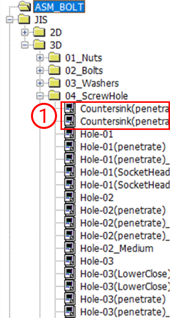
- (1)Select one of the following
- – Countersink (penetrate)
- – Countersink (penetrate)_Medium
- 2) If you use user-defined, set the variable as follows
- – l,dk,dn,t
- – l,dk,d,d,t
|
|
| Non linkage hole e.g.,1 |
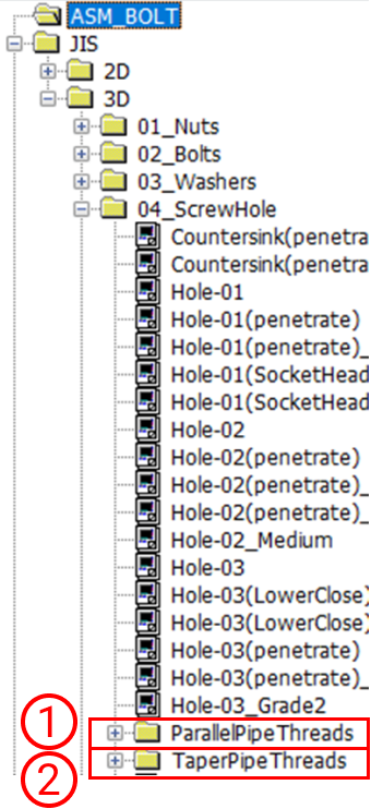 |
- Holes using the following hole commands are not eligible for linkage.
- (1)ParallelPipeThreads
- (2)TaperPipeThreads
|
If holes are made with these hole commands, they are not to be linked |
| Non linkage hole e.g.,2 |
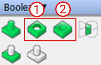 |
- Holes using the following hole commands are not eligible for linkage.
- ①Sabtract
- ②Subtract (Keep subtracted entities)
- Other machine parts are selected, and holes using other than “Arrange Part” are not to be linked.
|
If it is made with these hole commands, the message “Hole command not used” will be displayed. |