- HELP
- Technical Information
- Sheet metal
- Design Guidelines
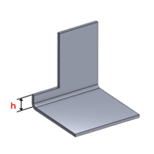
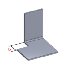
- Bending Conditions
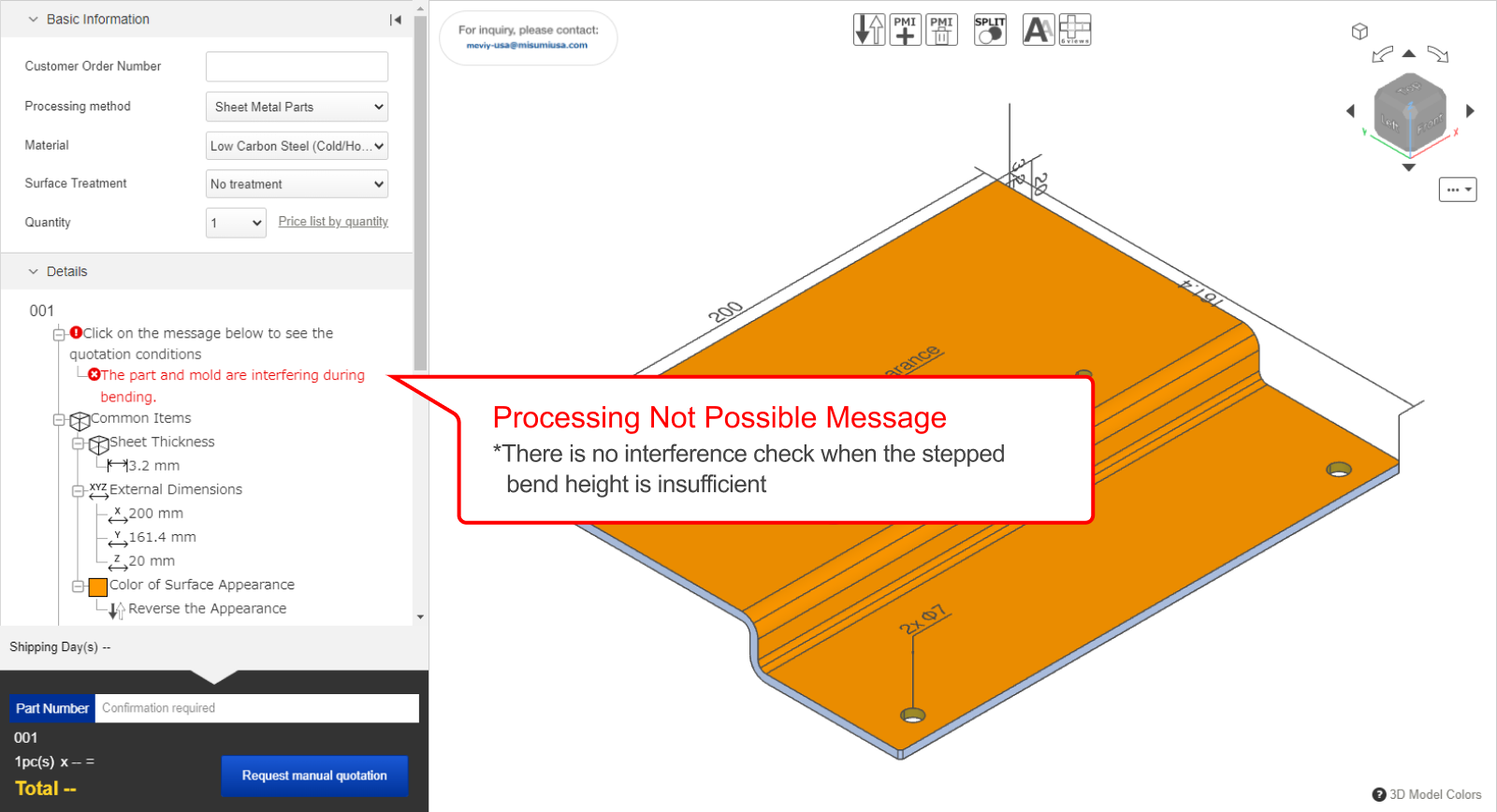
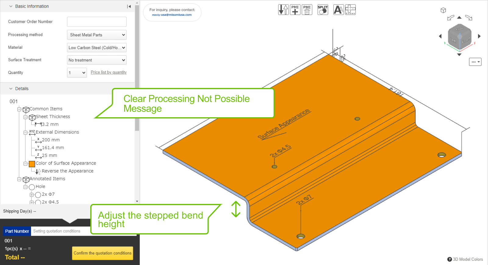
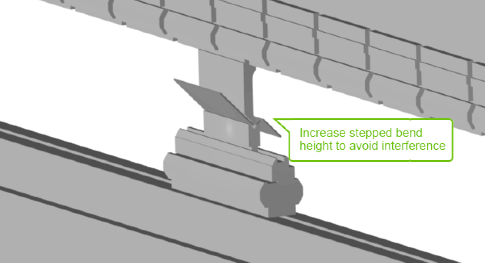
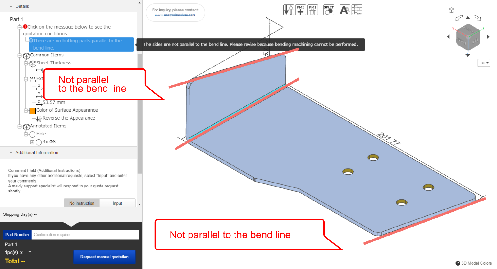
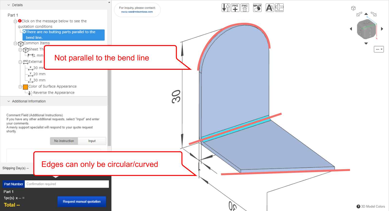
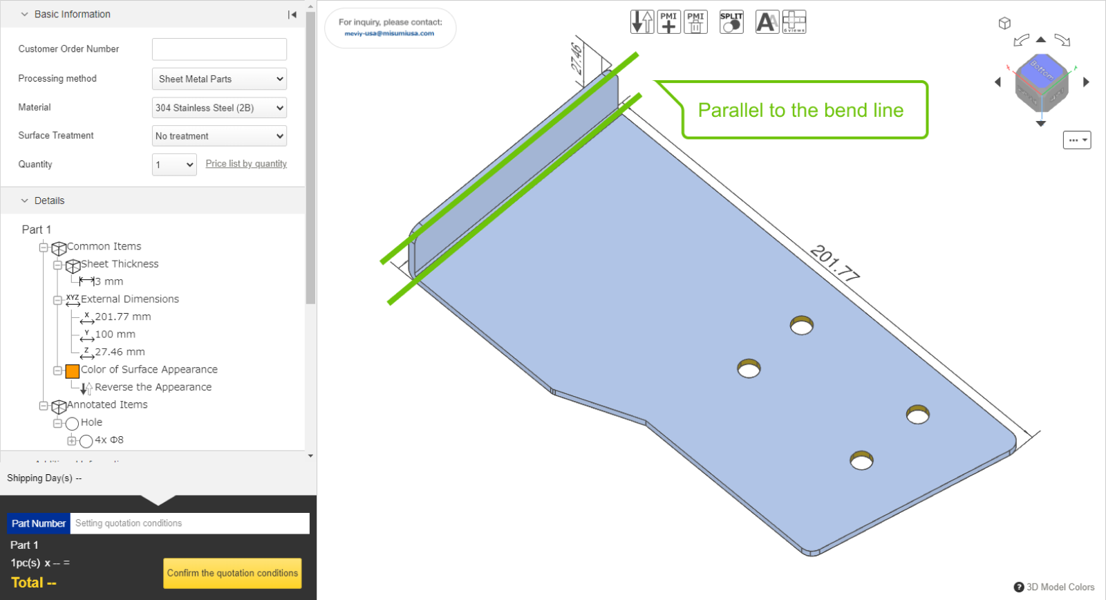
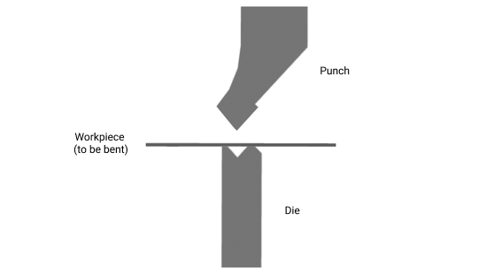
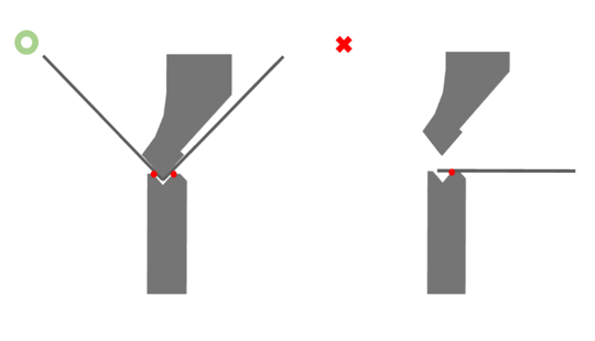
Bending Conditions
| Modeling Rules | Example |
|---|---|
|
 |
|
 |

| Modelling rules | Location |
|---|---|
|
 |
|
 |