- HELP
- How to use
- Quotation conditions settings
- [CNC Turning ] Quotation Settings
- Set datum and geometric tolerances
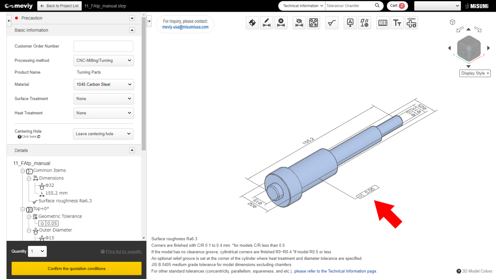
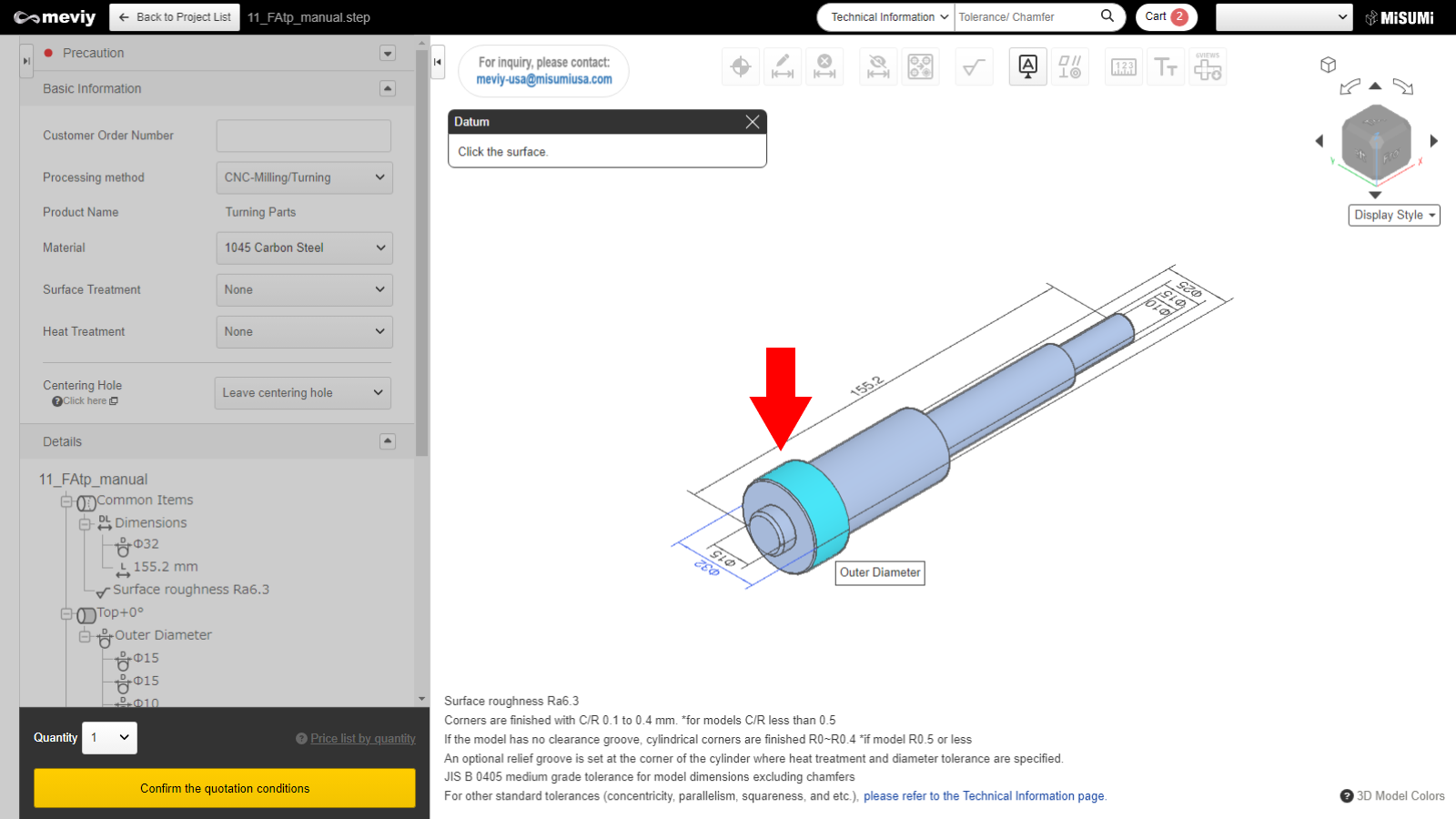
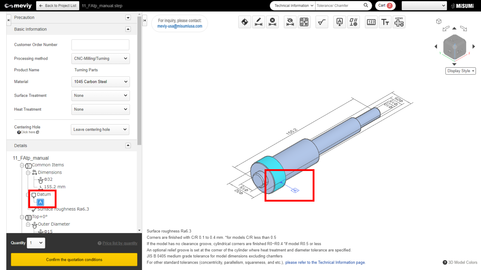
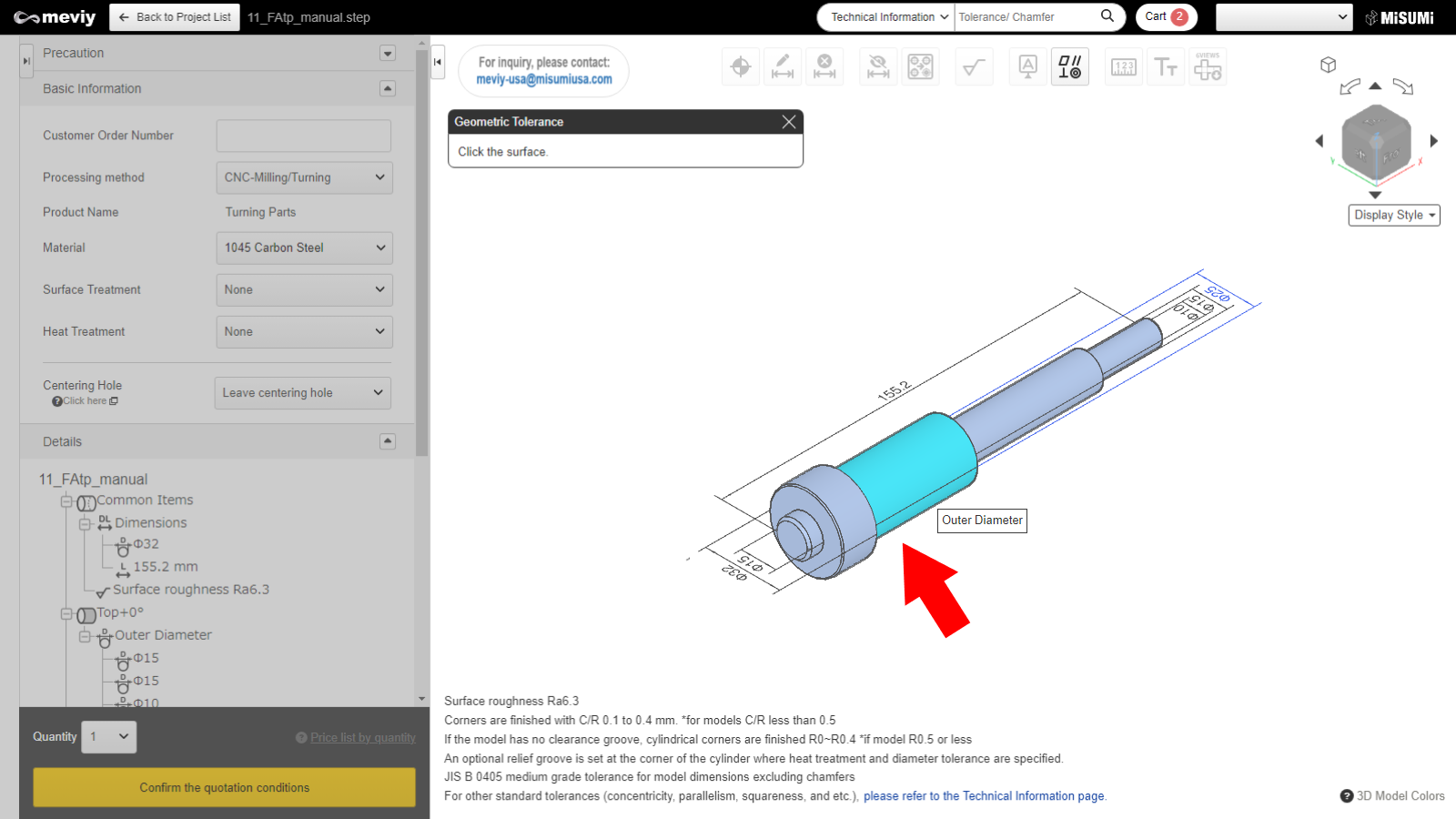
Set datum and geometric tolerances
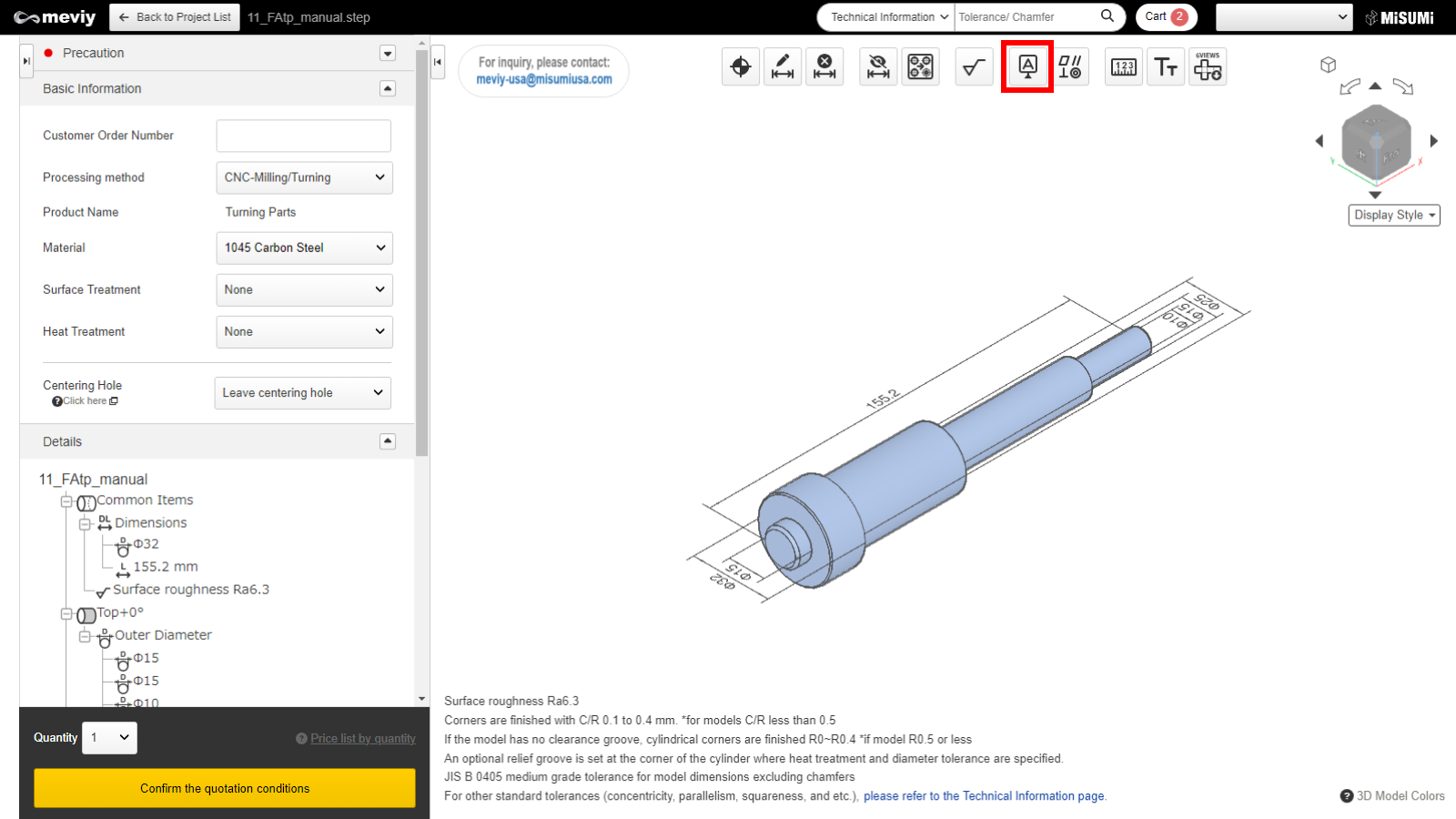
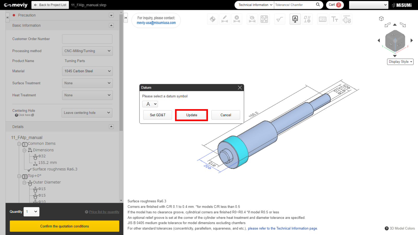
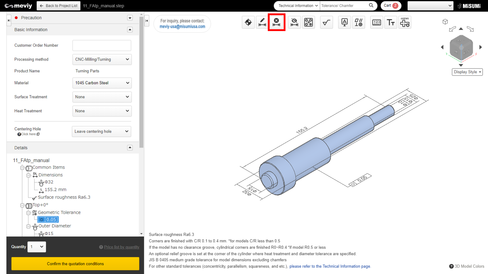
Select  from the icons at the top.
The shortcut (Shift + G) can also be used to select it.
Caution
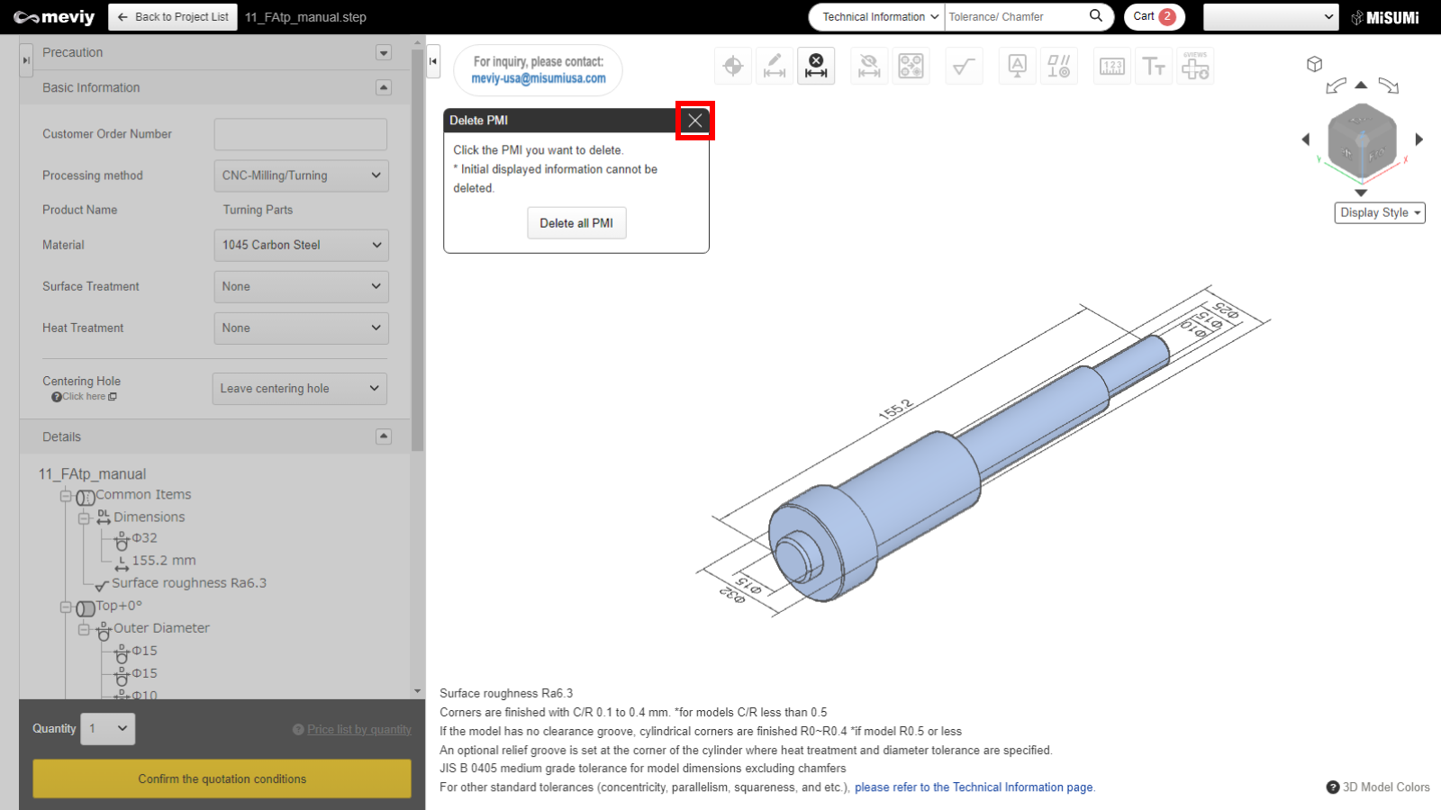
If the surface is not selectable, the “Not Selectable” icon will be displayed when the mouse hovers over it.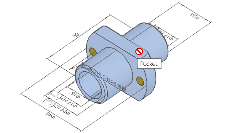
Tip
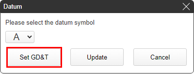
- Click the “Set GD&T” button instead of “Update” to set a geometric tolerance for the newly created datum.
- *The settings up to this step will be temporarily saved.
- Reference>>>How to set geometric tolerance STEP2

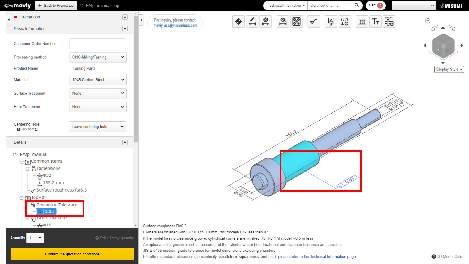
Select  from the icons at the top.
The shortcut key (G) can also be used to select it.
Caution
If the surface is not selectable, the “Not Selectable” icon will be displayed when the mouse hovers over it.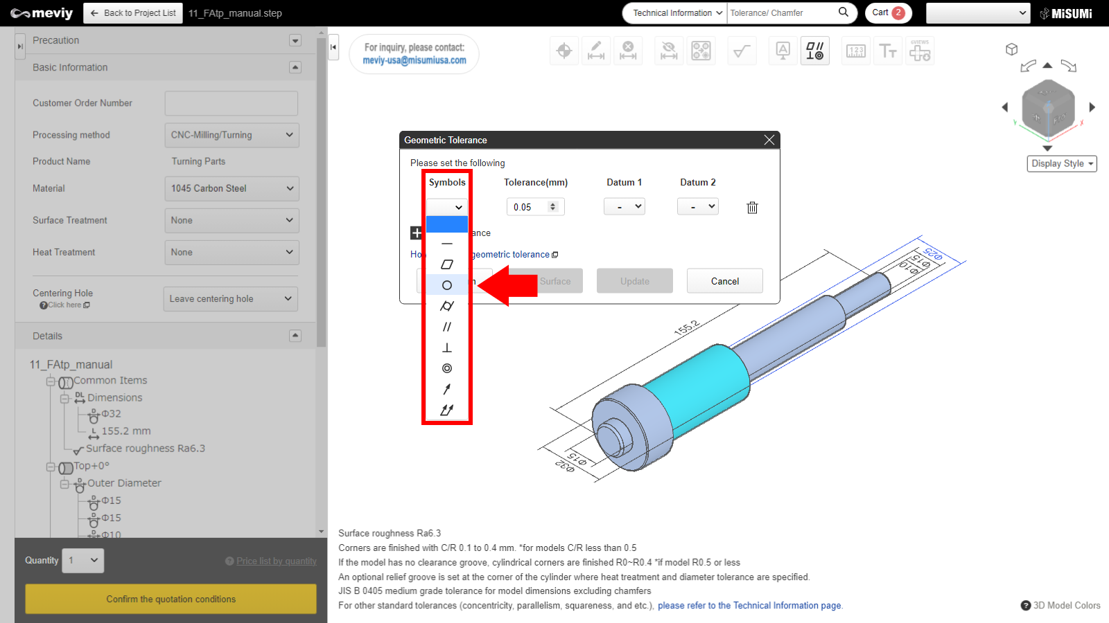
Geometric tolerance types that can be specified are as follows.
| Icon | Flat surface | Cylindrical face | Datum | |
|---|---|---|---|---|
| Flatness | 〇 | – | – | |
| Parallelism | 〇 | – | Required | |
| Perpendicularity | 〇 | 〇 | Required | |
| Circularity | – | 〇 | – | |
| Concentricity | – | 〇 | Required | |
| Straightness | – | 〇 | – | |
| Cylindricity | – | 〇 | – | |
| Circular runout | – | 〇 | Required | |
| Total runout | – | 〇 | Required |
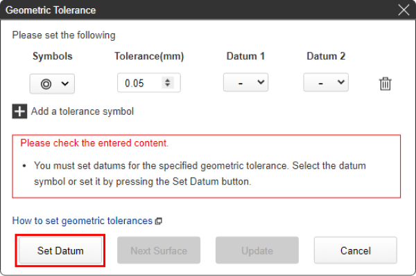
Tip
- You can specify a new datum by clicking the “Set Datum” button in the lower left corner, even if you have not completed datum settings.
- *The settings up to this step will be temporarily saved.
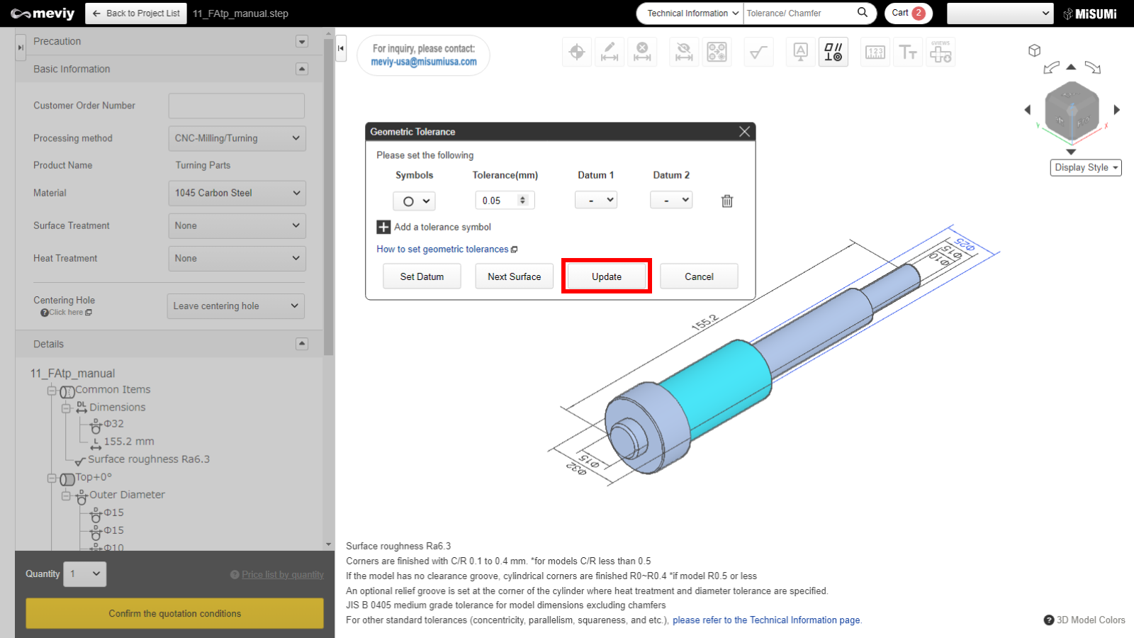
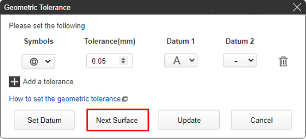
Tip
- If you press the “Select next surface” button without pressing Update, you can set a new geometric tolerance on another surface.
- *The settings up to this step will be temporarily saved.
Select  from the icons at the top.
The shortcut key (D) can also be used to select it.