- HELP
- How to use
- Quotation conditions settings
- [CNC Turning ] Quotation Settings
- How to Use the 3D Viewer
How to Use the 3D Viewer
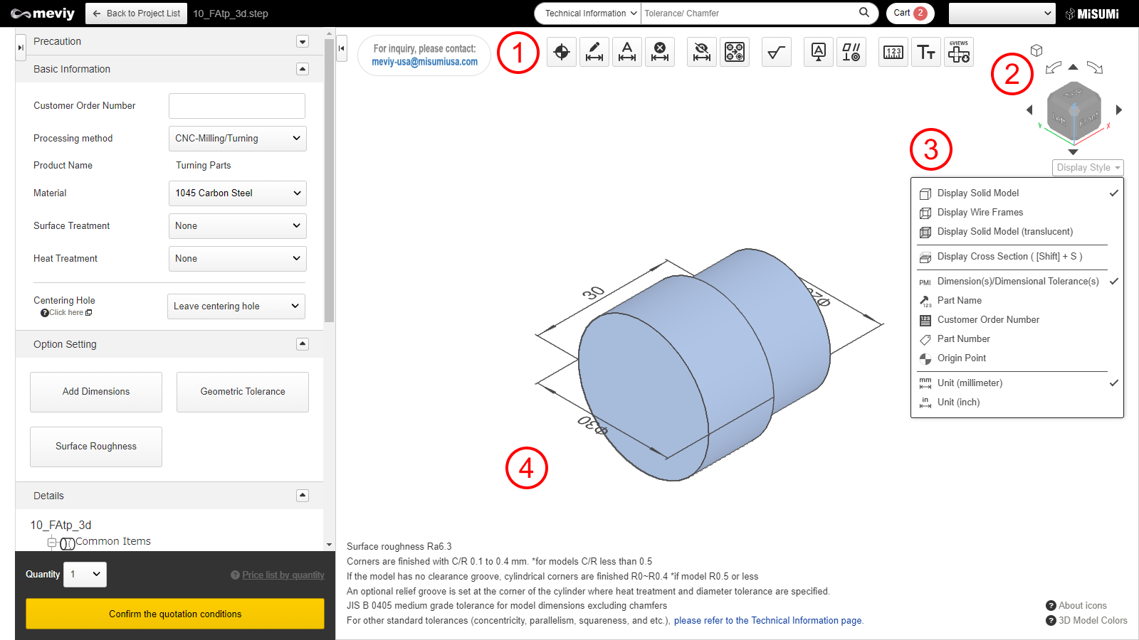

| Function Name | What You Can Do |
|---|---|
Designate Design Origin |
Move the design’s origin point. → Change a Design’s Origin |
Add Dimensions |
Add dimensions and dimensional tolerances. → Add/Remove Dimensions and Dimensional Tolerances |
Add Dimensions in Batch |
Batch add coordinate dimensions. → Adding Dimensions*No dimensions will be added to faces which are at an oblique angle. |
Delete PMI |
Remove added dimensions. → Add/Remove Dimensions and Dimensional Tolerances |
Hide dimensions |
Hides dimensional tolerances guaranteed by “Default General Tolerance Standards for Machined Dimensions.” |
Split Grouped Holes |
You can split holes grouped during shape recognition. → Splitting Grouped Holes |
| Function Name | What You Can Do |
|---|---|
Measurement |
This function allows measurement of models uploaded. → Measuring 3D models」 |
Set Surface Roughness |
Surface roughness can be set. → Set Surface Roughness |
Change Font Size |
You can change the font size of the PMI display. → Changing Font Sizes |
Simple 2D Drawing |
Download image files that capture each orthogonal direction of the 3D models and arrange them via 3rd angle projection. |
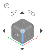
- Rotate the cube to change the orientation of the currently displayed parts.
- Click
 [Isometric View] to return to the isometric view (default orientation).
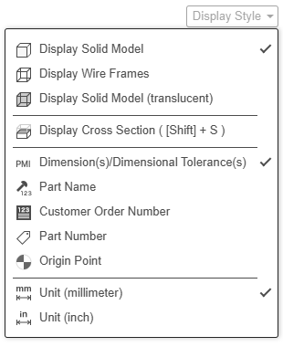
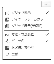
- Move the mouse over the
 icon to display the display settings menu.
 - Here you can change the 3D model display method, and also toggle between displaying or hiding text information in the 3D viewer.