- HELP
- Technical Information
- CNC Milling
- Design Guidelines
- Recognizing Different Types of Hole
Recognizing Different Types of Hole
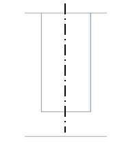
| Blind cylindrical shape with flat hole base |
 |
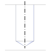
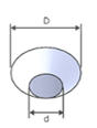
| Blind cylindrical shape with conical hole base |
 |
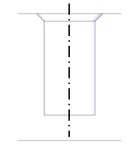
| Blind cylindrical shape with flat hole base +90° chamfer at entrance |
 |
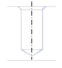
| Blind cylindrical shape with conical hole base +90° chamfer at entrance |
 |
| Through cylinder |
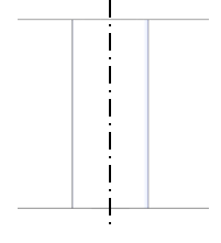 |
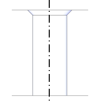
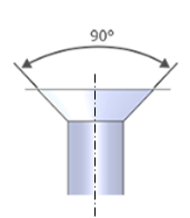
| Through cylinder +90° chamfer at entrance |
 |
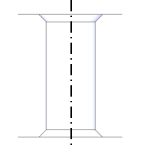
| Through cylinder +90° chamfer at entrance (both sides) |
 |
| One-step hole |
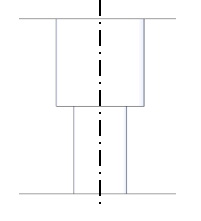 |
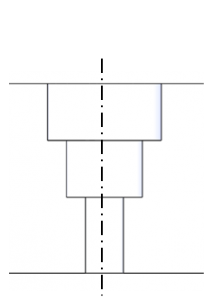
Two-step hole |
 |

 |
 |
| Decreasing two-step hole |
 |
| Non-90° entrance chamfer |
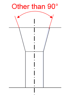 |
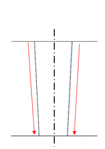
| Tapered hole |
 |
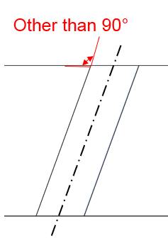
| Oblique hole |
 |
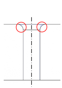
| Fillet at entrance |
 |
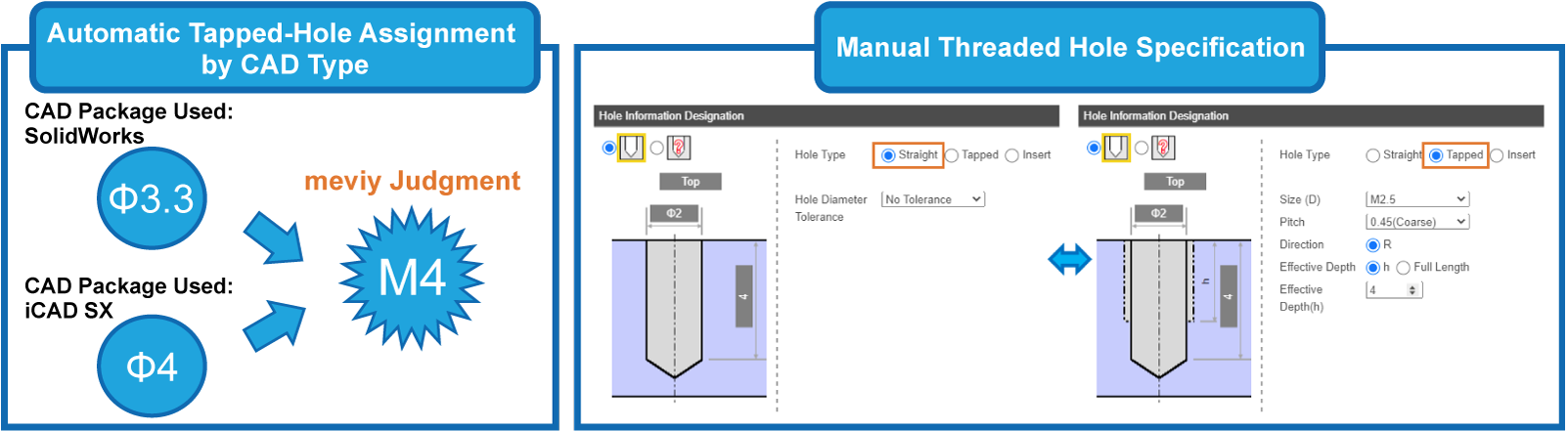
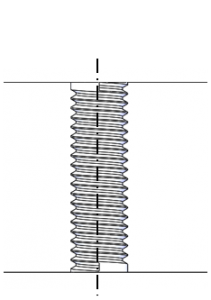
| Machined thread |
 |
| Through-hole shape with width = 2R |
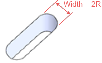 |
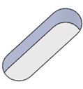
Through-hole shape with width = 2R, |
 |
| Through-hole shape with width = 2R, +90° chamfer at entrance (both sides) |
 |
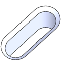
| Blind hole with width = 2R |
 |
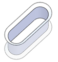
| Blind hole with width = 2R, +90° chamfer at entrance |
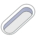 |
| +90° U-shaped through slot where width = 2R |
 |
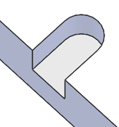
| U-shaped through slot with width = 2R, with 90° chamfer at entrance (one side) |
 |
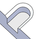
| U-shaped through slot with width = 2R, +90° chamfer at entrance (both sides) |
 |
| U-shaped blind slot with width = 2R |
 |
| U-shaped blind slot with width = 2R +90° chamfer at entrance |
 |