Friction Drilled/Tapped Holes Modeling and Sizes

Inch Thickness Gauge Standard

Friction Drilled Tapping is not applicable for Inch Thickness Sheetmetal

Metric Thickness Gauge Standard

Friction Drilled Tapping Holes Modeling Rules

When a cylindrical flange shape element is detected, it will be identified as a friction drilled/tapped hole.

Modeling Rules Example
The inner diameter (d) should follow the same rules as for Tapped Hole Identification described above. Model the flange height (h) and thickness (t) to be less than or equal to the Sheet Thickness.
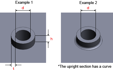
 Example

Friction Drilled/Tapped Hole Size Selection

Friction drilled/tapped holes cannot be selected for perforated metals, shim plate materials (Cold Rolled Low Carbon Steel (for Shims) or 304 Stainless Steel (H) (for Shims)) or clear resin.
Material Plate Thickness Friction Drilled/Tapped Hole Diameter(*1)
  • EN 1.0330 equiv.
  • EN 1.0320 equiv. (hot coiled)
  • EN 1.0330 equiv. (Electrolytic Zinc Plating)
0.8 M3 M4
1.0 M2​ M2.5​ M3 M4 M5
1.2 M2​ M2.5​ M3 M4 M5
1.6 M2​ M2.5​ M3 M4 M5
  • EN 1.4301 equiv.(2B)
  • EN 1.4301 equiv. (single-sided #400-grit polished)
  • EN 1.4301 equiv.(single-sided hairline finish)
  • EN 1.4016 equiv.
  • EN AW−5052 equiv.
0.8 M3 M4
1.0 M3 M4 M5
1.2 M3 M4 M5
1.5 M3 M4 M5

*1 M2 and M2.5 are limited to Cold Rolled Low Carbon Steel (hot galvanized) and Cold Rolled Low Carbon Steel (electrolytic galvanized).