The cutting service does not display dimensions or tolerances when 3D CAD data is uploaded other than external dimensions and hole information, assuming that the customer specifies tolerances of their choice.
This section describes the finish of parts where dimensions and tolerances are not displayed.
Default General Tolerance Standards for Machined Dimensions (Standard products conform to JIS B 0405:1991/JIS B 0419:1991, International Economy products conform to the standards of the country of manufacture.)
The following standards are applied to the origin according to machining standards.
The origin can be moved to any position.
Length, Excluding Chamfer, Dimensional Tolerances
[mm]
Product lineup
Tolerance Grade
Base Dimensions
Symbol
Description
≥0.5 ≤3
>3 ≤6
>6 ≤30
>30 ≤120
>120 ≤400
>400 ≤1000
Standard
m
Medium
±0.1
±0.1
±0.2
±0.3
±0.5
±0.8
International Economy
–
–
±0.1
±0.1
±0.2
±0.3
±0.5
±0.8
Tolerances for Chamfer Length Dimensions (Corner Radius or Corner Chamfer Dimensions)
[mm]
Product lineup
Tolerance Grade
Base Dimensions
Symbol
Description
≥0.5 ≤3
>3 ≤6
>6
Standard
C
Rough
±0.4
±1
±2
International Economy
–
–
±0.4
±1
±2
Angle Dimensional Tolerances
[mm]
Product lineup
Tolerance Grade
Length of the Shorter Angle Edge
Symbol
Description
≤10
>10 ≤50
>50 ≤120
>120 ≤400
>400
Standard
m
Medium
±1°
±30′
±20′
±10′
±5′
International Economy
–
–
±1°
±30′
±20′
±10′
±5′
General Tolerances of Perpendicularity
[mm]
Product lineup
Tolerance Grade
Nominal Length of the Shorter Edge
Symbol
≤100
>100 ≤300
>300 ≤1,000
Standard
K
0.4
0.6
0.8
International Economy
–
0.4
0.6
0.8
General Tolerances of Straightness and Flatness
[mm]
Product lineup
Tolerance Grade
Nominal Length
Symbol
≤10
>10 ≤30
>30 ≤100
>100 ≤300
>300 ≤1,000
Standard
K
0.05
0.1
0.2
0.4
0.6
International Economy
–
0.05
0.1
0.2
0.4
0.6
(Related) Changing a design’s origin.
Width (Y) and thickness (Z) tolerances of polished flat bar
The following standards are applied to polished flat bars, depending on the material. As for tolerances for overall length (X) and other dimensions, “Standard for normal tolerances for machining dimensions without indication (extracted from JIS B 0405:1991/JIS B 0419:1991)” is applied as in the case of other materials.
1018 Carbon Steel (polished), 1045 Carbon Steel (polished), 304 Stainless Steel (polished) Excerpt from JIS G 3123:2004 / JIS G 4318:2016
Tolerance Grade
Width Tolerance/Thickness Tolerance
Symbol
Description
>
3
6
10
18
30
50
80
120
≤
6
10
18
30
50
80
120
180
IT
13
-0.18~0
-0.22~0
-0.27~0
-0.33~0
-0.39~0
-0.46~0
-0.54~0
-0.63~0
6063 Aluminum Alloy, Excerpt from JIS H 4040:2015
Thickness
Width
Thickness Tolerance
Width Tolerance
Thickness
Width
Thickness Tolerance
Width Tolerance
5
15
±0.26
±0.33
12
12
±0.33
±0.33
20
±0.39
15
30
20
±0.39
±0.39
40
±0.33
±0.52
30
50
40
±0.52
60
±0.78
50
100
±1.00
60
±0.46
±0.78
6
15
±0.26
±0.33
100
±0.52
±1.00
20
±0.39
15
15
±0.39
±0.39
30
20
40
±0.33
±0.52
30
50
40
±0.52
60
±0.78
50
±0.52
100
±1.00
60
±0.46
±0.78
8
15
±0.33
±0.33
100
±0.52
±1.00
20
±0.39
20
20
±0.39
±0.39
30
30
40
±0.52
40
±0.46
±0.52
50
50
60
±0.39
±0.78
60
±0.52
±0.78
100
±0.46
±1.00
100
±0.59
±1.00
10
10
±0.33
±0.33
25
25
±0.39
±0.39
15
30
20
±0.39
40
±0.46
±0.52
30
50
40
±0.52
60
±0.52
±0.78
50
100
±0.59
±1.00
60
±0.39
±0.78
30
30
±0.46
±0.46
100
±0.46
±1.00
40
±0.52
50
60
±0.52
±0.78
100
±0.59
±1.00
Resin Precision Assurance
Unlike metal, resin is a material that easily changes shape or dimensions due to factors such as temperature and humidity. Due to this, precision assurance is performed under the following conditions: · Inspections are performed in temperature-controlled environments. · Precision assurance is based on the results of inspections performed immediately before shipment.
Surface Roughness
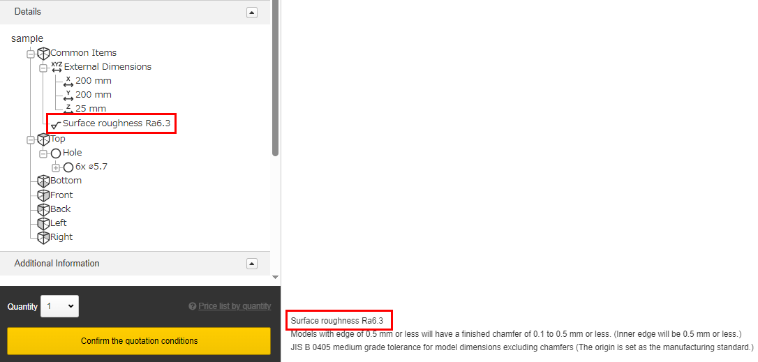
The default surface roughness reference value is √Ra6.3 (√Rz25).
A value of 6.3 or 3.2 can be specified when the surface roughness symbol “Ra” is selected in the user settings or initial quotation conditions.
A value of 25 or 12.5 can be specified if “Rz” is selected.
The surface roughness is displayed in the tree view and in the lower left corner of the model viewer.
Surface Roughness
Symbol
Selected Value
Ra
6.3
3.2
Rz
25
12.5
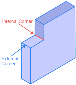
Internal and External Corners
For external sharp corners or corners of C0.5 and smaller, the finish will be as follows: · Corners C0.1 mm to 0.5 mm or less
For internal sharp corners, the finish will be as follows: · Internal corners R0.1 to R0.5 mm or less