- HELP
- Technical Information
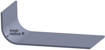
- Sheet metal
- Applicable parts/Materials
- Target Range for R-Bending (Large Radius)
Target Range for R-Bending (Large Radius)
Applicable sheet thickness and Radius size for R-bend shapes
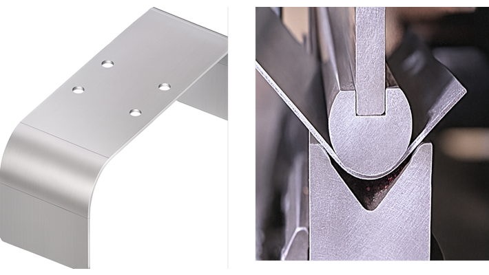
- R-bend shapes are generally manufactured using a feed bending process. This creates continuous tool marks that remain on the bent part. For details, please see “Bending Specifications“.
- If feed bending is difficult, we will propose radius sizes for which normal bending or special R-bend tools can be used. If this is acceptable, we will automatically change the R size on the meviy part.
- For details, please refer to the R-size conversion table below.
Metric Thickness - Inner R range
| Plate thickness | Minimum inner R | Maximum inner R |
|---|---|---|
| 0.8 | 10 | 150 |
| 1.0 | 10 | 150 |
| 1.2 | 10 | 150 |
| 1.5 | 10 | 150 |
| 1.6 | 10 | 150 |
| 2.0 | 10 * | 150 |
| 2.3 | 15 | 150 |
| 2.5 | 10 | 150 |
| 3.0 | 30 | 150 |
| 3.2 | 30 | 150 |
* Steel material is R15 as minimum inner R.
*R-size conversion table for when Feed bending is not possible.
| Inner R size before conversion | Inner R size after conversion | Bending process used |
|---|---|---|
| Within twice the sheet thickness | Thickness (reference value) | Normal Bending |
| Less than R3 | Thickness (reference value) | |
| R3 ≤ R < R6 | R3 | R-bending with special tools |
| R6 ≤ R < R10 | R6 | |
| R10 ≤ R < R12.5 | R10 | |
| R12.5 ≤ R < R15 | R12.5 | |
| R15 ≤ R < R17.5 | R15 | |
| R17.5 ≤ R < R20 | R17.5 | |
| R20 ≤ R < R22.5 | R20 | |
| R22.5 ≤ R < R25 | R22.5 | |
| R25 ≤ R < R30 | R25 | |
| R30 ≤ R |
| ー |
Inch Thickness - Inner R range
| Plate thickness | Minimum inner R | Maximum inner R |
|---|---|---|
| #24 | 0.394″ | 5.905″ |
| #22 | 0.394″ | 5.905″ |
| #20 | 0.394″ | 5.905″ |
| #19 | 0.394″ | 5.905″ |
| #18 | 0.394″ | 5.905″ |
| #16 | 0.394″ | 5.905″ |
| #14 | 0.394″ | 5.905″ |
| #13 | 0.394″ | 5.905″ |
| #12 | 0.394″ | 5.905″ |
| #11 | 0.181″ | 5.905″ |
Applicable materials and surface treatments for R-bend shapes
Materials and surface treatments available for R bending are as follows.
Metric Thickness Gauge Standard
| Material: Ferrous Metals | Surface Treatment | R bending available | |
|---|---|---|---|
| Feed Bending | R-bending with special tools | ||
| Low Carbon Steel (Cold/Hot Rolled) | – | Automatic Quotation | Automatic Quotation |
| Powder Coating | |||
| Wet Paint | |||
| Electroless Nickel Plating | |||
| Black Oxide | |||
| Trivalent Chromate (Clear) | |||
| Trivalent Chromate (Black) | Automatic Quotation | Manual Quotation | |
| Cold Rolled Low Carbon Steel (Electrolytic Zinc Plating) | Electrolytic Zinc Plating | Automatic Quotation | Automatic Quotation |
| Cold Rolled Low Carbon Steel (Galvanized) | Hot Zinc Plating | ||
| Material: Stainless Steel | Finishing Method | R bending available | |
|---|---|---|---|
| Feed Bending | R-bending with special tools | ||
| 304 Stainless Steel | 2B | Automatic Quotation | Automatic Quotation |
|
Manual Quotation | ||
|
Manual Quotation | Not supported | |
| 430 Stainless Steel | 2B | Automatic Quotation | Automatic Quotation |
| Material: Aluminum | Surface Treatment | R bending available | |
|---|---|---|---|
| Feed Bending | R-bending with special tools | ||
| 5052 Aluminum Alloy | — | Automatic Quotation | Automatic Quotation |
| Clear Anodize | |||
| Black Anodize | |||
| Black Anodize (matte) | |||
| Trivalent Chromate Passivation | |||
| 5052 AL Alloy Pre-Finish, Clear Anodize | Clear Anodize | ||
| 5052 AL Alloy Pre-Finish, Black Anodize | Black Anodize | ||
| Material: Perforated Metal | Hole Diameter × Hole Pitch | R bending available | |
|---|---|---|---|
| Feed Bending | R-bending with special tools | ||
| ø1 × 2p | Automatic Quotation | Automatic Quotation |
| ø2 × 3p | |||
| ø3 × 5p | |||
| ø5 × 8p | |||
| ø8 × 12p | |||
Inch Gauge Standard (FR bending only)
| Material: Ferrous Metals | Surface Treatment | Sheet Thickness (Inch) *1 | (mm) | External Dimensions *2 *4 | |||
|---|---|---|---|---|---|---|---|
| Length | Width | Height | |||||
|
Low Carbon Steel (Cold/Hot Rolled) |
– | 0.0299″ (#22), 0.0359″ (#20), 0.0418″ (#19), 0.0478″ (#18), 0.0538″ (#17), 0.0598″ (#16), 0.0747″ (#14), 0.0897″ (#13), 0.1046″ (#12), 0.1196″ (#11) | 0.759mm (#22), 0.912mm (#20), 1.062mm (#19), 1.214mm (#18), 1.367mm (#17), 1.519mm (#16), 1.897mm (#14), 2.278mm (#13), 2.657mm (#12), 3.038mm (#11) | 5–1500mm (59.05″) | |||
| Paint *3 | |||||||
| 5–1500mm (59.05″) | 5–1500mm (59.05″) | 5–1500mm (59.05″) | |||||
| Black Oxide | 5–609.6mm (24″) | 5–609.6mm (24″) | |||||
| Trivalent Chromate (Clear) | 5–1500mm (59.05″) | 5–584mm (23″) | 5–813mm (32″) | ||||
| Trivalent Chromate (Black) | |||||||
| Low Carbon Steel (Cold Rolled) | Electrolytic Galvanized *5 | 0.0336″ (#22), 0.0396″ (#20), 0.0516″ (#18), 0.0635″ (#16), 0.0785″ (#14) | 0.701mm (#24), 1.006mm (#20), 1.311mm (#18), 1.613mm (#16), 1.994mm (#14) | 5–1500mm (59.05″) | |||
| Hot Galvanized *5 | 0.0276″ (#24), 0.0336″ (#22), 0.0516″ (#18), 0.0635″ (#16), 0.0785″ (#14) | 0.701mm (#24), 0.853mm (#22), 1.311mm (#18), 1.613mm (#16), 1.994mm (#14) | 5–1500mm (59.05″) | ||||
| Material: Stainless Steel | Surface Finish | Sheet Thickness (Inch) *1 | (mm) | External Dimensions *2 *4 | |||
|---|---|---|---|---|---|---|---|
| Length | Width | Height | |||||
|
2B | 0.0312″ (#22), 0.0375″ (#20), 0.0437″ (#19), 0.0500″ (#18), 0.0625″ (#16), 0.0781″ (#14), 0.0937″ (#13), 0.1094″ (#12), 0.1250″ (#11) | 0.792mm (#22), 0.953mm (#20), 1.110mm (#19), 1.270mm (#18), 1.588mm (#16), 1.984mm (#14), 2.380mm (#13), 2.779mm (#12), 3.175mm (#11) | 5–1500mm (59.05″) | |||
| Single Sided #4 Brushed *6 | 0.0312″ (#22), 0.0375″ (#20), 0.0437″ (#19), 0.0500″ (#18), 0.0625″ (#16), 0.0781″ (#14), 0.0937″ (#13) | 0.792mm (#22), 0.953mm (#20), 1.110mm (#19), 1.270mm (#18), 1.588mm (#16), 1.984mm (#14), 2.380mm (#13) | |||||
| Material: Aluminum Alloy | Surface Treatment | Sheet Thickness (Inch) *1 | (mm) | External Dimensions *2 *4 | |||
|---|---|---|---|---|---|---|---|
| Length | Width | Height | |||||
| 5052 Aluminum Alloy | — | 0.025″, 0.032″, 0.040″, 0.050″, 0.063″, 0.080″, 0.090″, 0.100″, 0.125″ | 0.635mm, 0.813mm, 1.016mm, 1.270mm, 1.600mm, 2.032mm, 2.286mm, 2.540mm, 3.175mm | 5–1500mm (59.05″) | |||
| Anodize (Clear) | 5–914.4mm (36″) | 5–609.6mm (24″) | |||||
| Anodize (Black) | |||||||
- *1 The plate thickness tolerance is ±10% (reference value).
- *2 The maximum and minimum dimensional values are limited by the shape of the bend.
- *3 Select a paint color from the table (Appendix Table).
- *4 The maximum length and width dimensions (Appendix Table) may vary depending on the surface treatment.
- *5 The machining surface will not be plated as it is a pre-treatment material.
- *6 Protective sheets (one-side only) affixed.