- HELP
- Technical Information
- CNC Turning
- Design Guidelines
- Difference in Shapes Between the 3D Model and the Finished Product
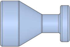
Difference in Shapes Between the 3D Model and the Finished Product

Notes
-
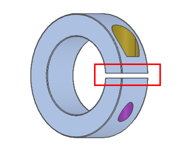
- A standard retaining ring grooving tool has corner R0.2
- For retaining ring standards, click here.>>>Specifications for External Thread and Internal Thread, Keyways, Holes and Pockets
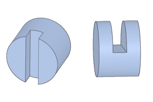
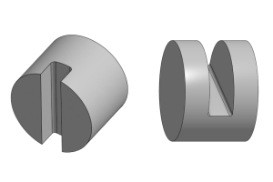
Outer diameter grooving

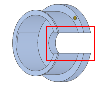
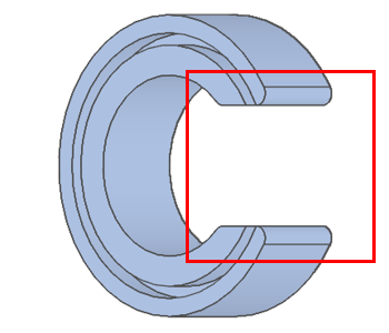
Inner diameter grooving

Caution
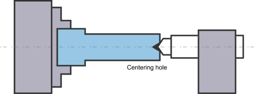
- “Centering hole cannot be left” can be selected, but there may be restrictions on the shapes that can be machined that make the option unavailable. When this occurs, check the “Important Information” in the upper-left corner of the screen.
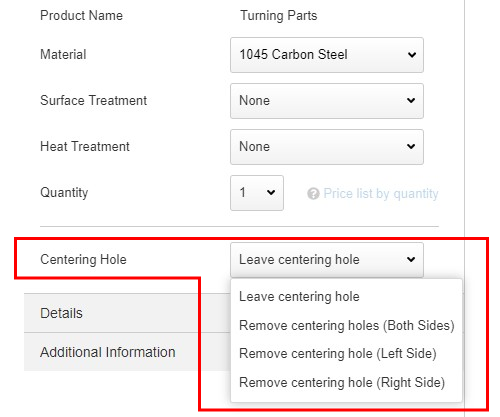
Notes
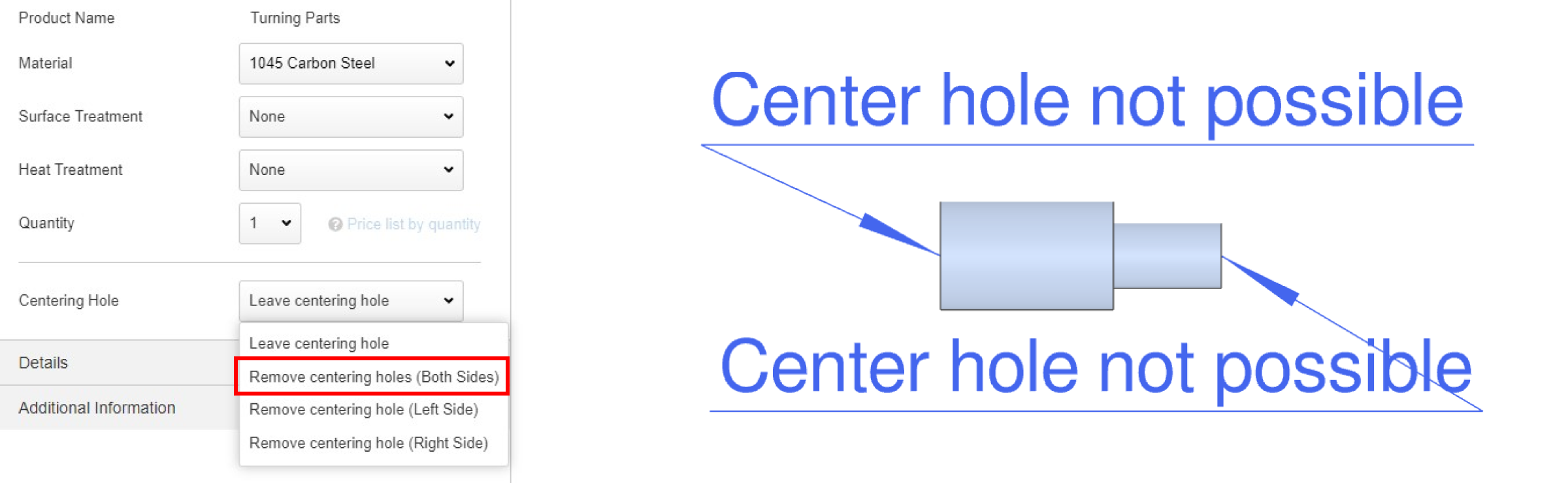
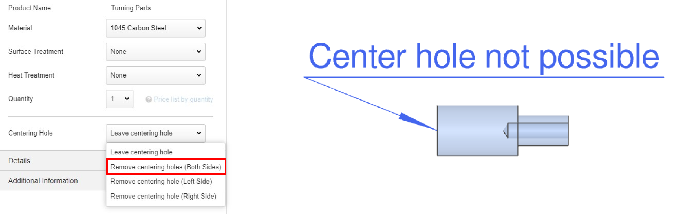
(1)When you select ”Remove centering hole”, an arrow will be shown on the model.
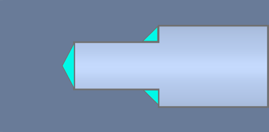
(2)When the model has an inner diameter, an arrow will not be shown on the model.
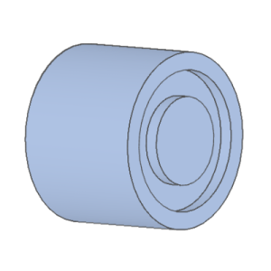
| Shape patterns | Inner diameter hole does not have a step | Inner diameter hole has a step |
|---|---|---|
| A |  |
 |
| Drill tip shape remains (flat bottom will be 1mm or more) | ||
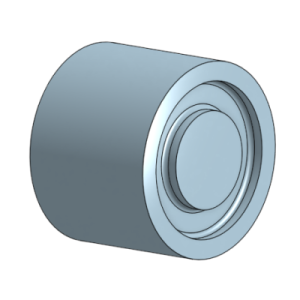
| B | 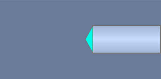 |
 |
| Drill tip shape remains, no flat bottom | ||
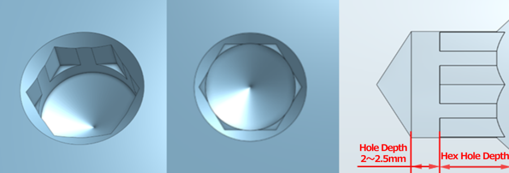
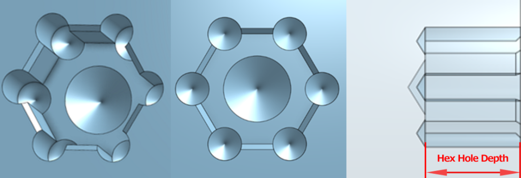
Notes
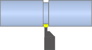
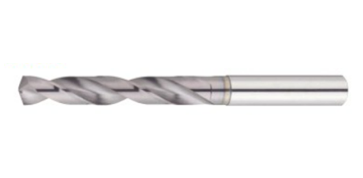
Machining drill reference photo
Tip
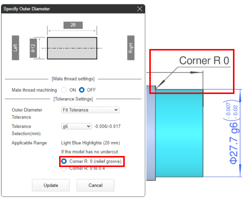
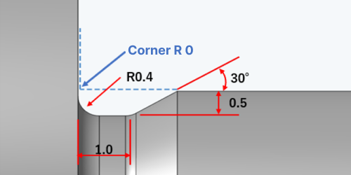
The width and depth of the relief added when selecting “Corner R0” can vary depending on the tools used. The exact dimensions cannot be specified.① Relief size when machining with R0.4 tools
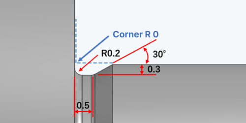
②Relief size when machining with R0.2 tools
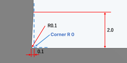
③ If the length of the shaft is short, it may be machined with a tool with a 0.1mm radius on the end that contacts the shaft.
Notes
In the following cases, “Corner R0” cannot be specified.
| (1) The model has Corner R0.5 or greater | (2) The model has a relief groove |
 |
 |
Tip
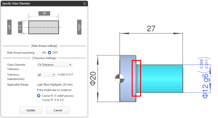
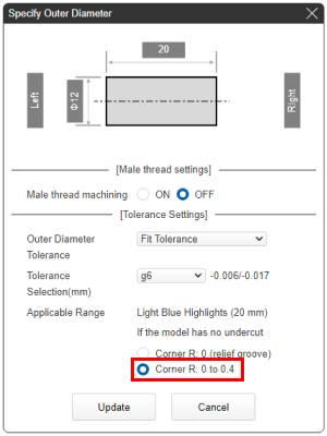
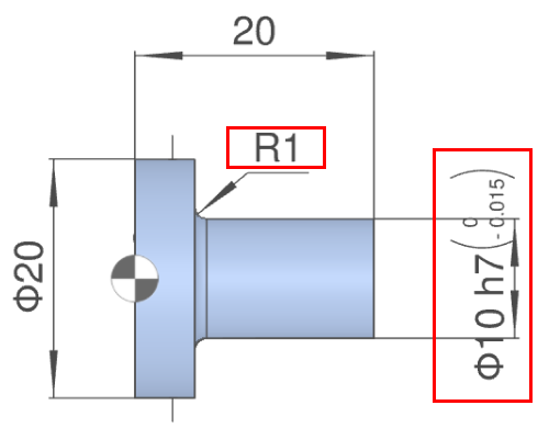
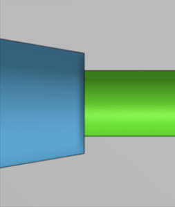
- Cylindrical corners with “Corner R0 to R0.4” can have the following shapes.
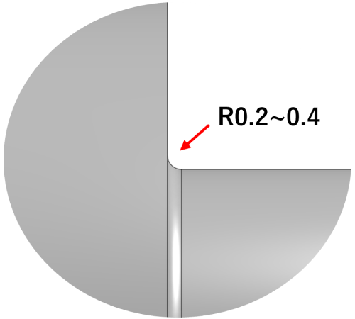
- ① Radius from machine tool remains.
- ② Relief groove is machined on the diameter only to achieve minimum clearance.
-
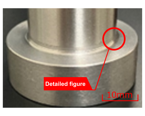
Machined diameter clearance groove.
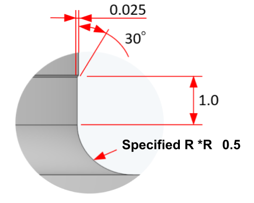
Groove Dimensions
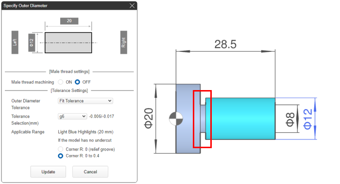
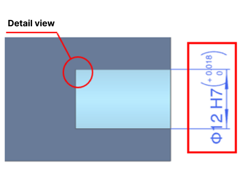
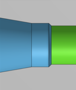
- ③ Relief groove is machined on the diameter and the face to achieve minimum clearance.
-
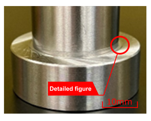
Machined diameter and face clearance grooves.
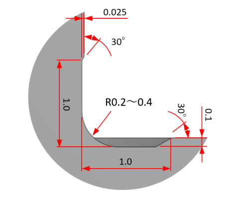
Groove Dimensions
If the corners are modeled with R0.5 or more, a relief groove will be machined to achieve minimum clearance.
 Modeled radius exceeds R0.5
- Machined diameter clearance groove.
- Groove Dimensions
Any of these corner conditions may be machined depending on the geometry.
 Sharp Corner, R0
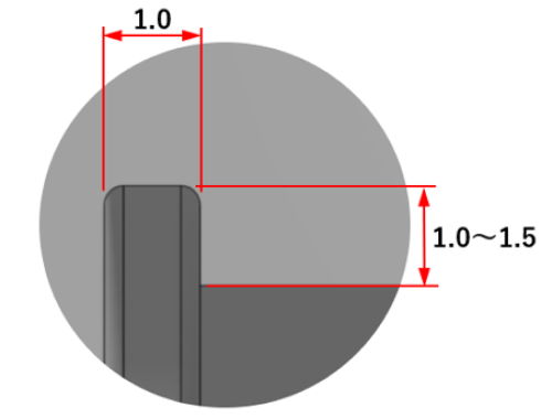 Undercut Groove
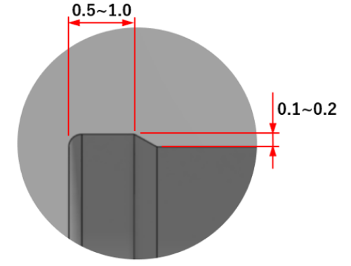 Undercut Groove with Lead
Notes
At the bottom left of the 3Dviewer, you can see the handling information for the cylindrical corners.
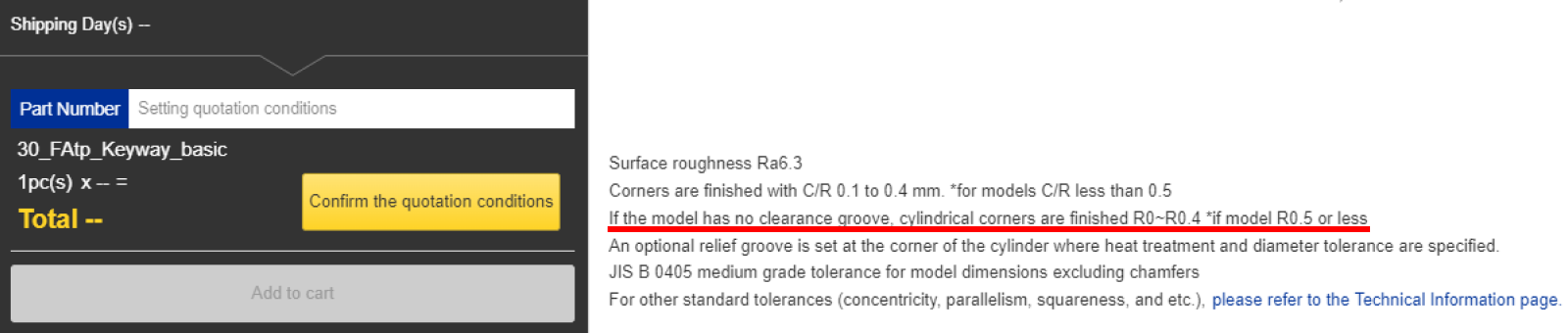
| External Thread | Internal Thread | ||
|---|---|---|---|
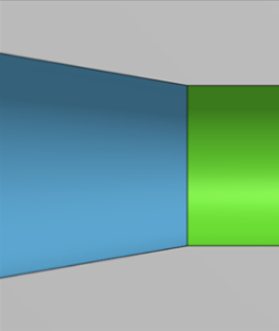
| Modelling | Without undercut | 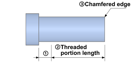 |
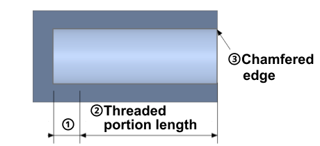 |
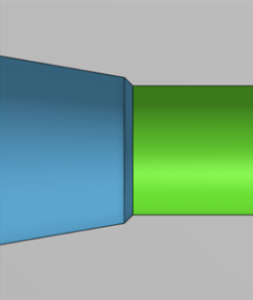
| With undercut |  |
 |
|
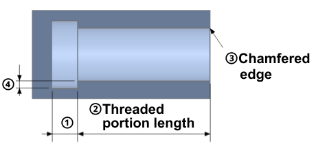
| (1) Lower limit value of incomplete threaded portion length and undercut width | Pitch × 2.0 | Pitch × 2.5 + 2 | |
| (2) Lower limit value of thread length (external thread) and thread depth (internal thread) | Pitch × 2.0 | Pitch × 2.0 | |
| (3) Chamfered edge | Chamfered to prevent burrs | Chamfered to prevent burrs | |
| (4) Minimum undercut depth value | Pitch × 0.75 | Pitch × 0.75 | |
Caution
④Models for which “pitch × 0.75” or less is set for the (4) minimum undercut depth value can be machined, but machine marks will remain.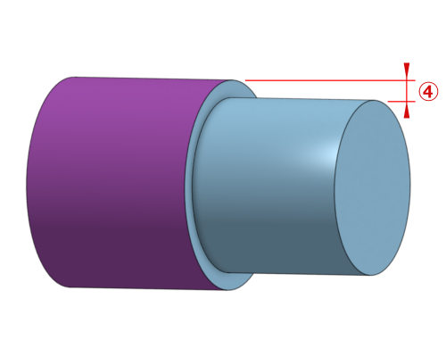 Reference model
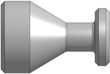
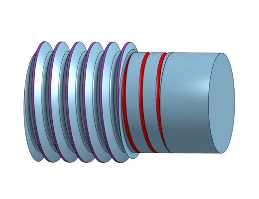 Actual finished shape after machining
Tip
- The [Notes] shown in the red box below describe the applicable thread length/thread depth.
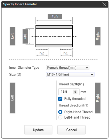
| Example 1) Outer diameter specification: male thread thread length 36.6mm = 44.6mm – 4.0(pitch) × 2.0 | Example 2) Inner diameter specification: female screw thread depth 11.0mm = 15.5mm – (1.0(pitch) × 2.5 + 2.0) |
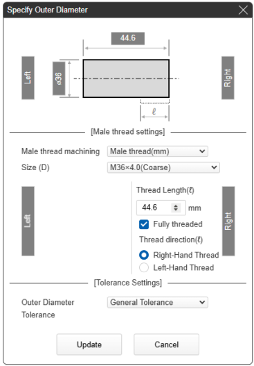 |
 |
Caution
- Modelled thread shape cannot be recognized. Specify the external thread and internal thread on the meviy screen.
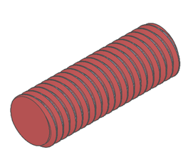

 Machined according to ISO standards (or JIS B 0203)
 Machined according to the model
Caution
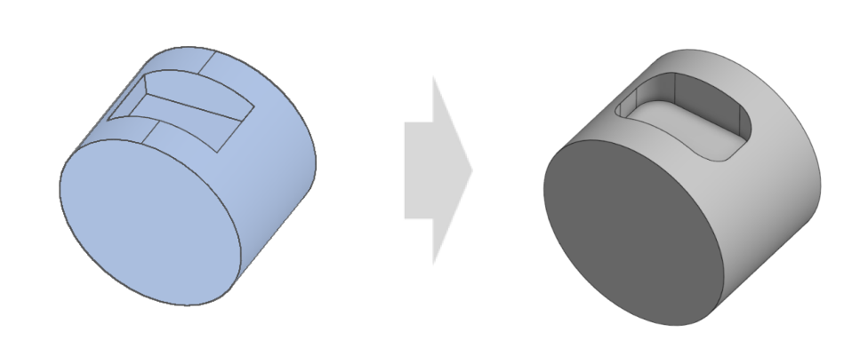
- The curved shape on the sides of the pocket is determined by the tool diameter, but we choose tools with the smallest possible diameter.
- If there are any discrepancies between the model and the finished shape, we will contact you to discuss it after the order is placed.