- HELP
- How to use
- Quotation conditions settings
- [CNC Milling] Quotation Settings
- Set datum and geometric tolerances
Set datum and geometric tolerances
Datum and geometric tolerances can be set.
How to set datum
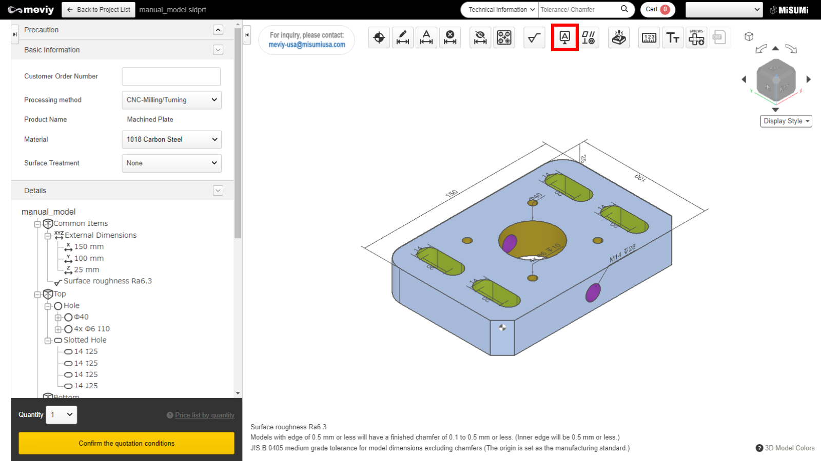
STEP1
Select  from the icons at the top.
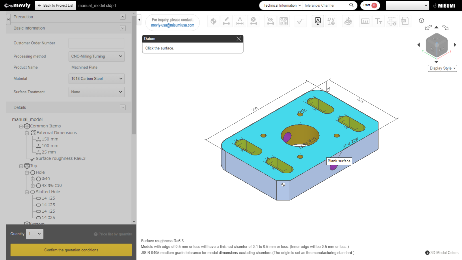
STEP2
Select the surface for which needs to be set the datum. The target area will be highlighted.
| Long dimension | Short dimension | Thickness | Tolerance lower limit | |
|---|---|---|---|---|
| Automatic Quotation | 10mm or more, 200mm or less | 8mm or more (maximum thickness of each material) | 0.02 | |
| Over 200mm, under 300mm | 0.03 | |||
| Over 300mm, under 400mm | 0.05 | |||
| Manual Quotation | Over 400mm, under 600mm Upper limit: 600mm x 400mm | 5mm or more, less than 8mm | 0.02 | |
Caution
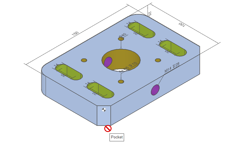
- In the following cases, the datum cannot be set and the button cannot be clicked.
- – The parts have a pocket(s) (excluding C-chamfer and fillet surfaces)
- – Any of the external dimensions is less than 10 mm
- – Any of the external dimensions is more than 300 mm
- Datum settings are not available for shapes, such as those containing pocket shapes within the part.
- If the surface is not selectable, the “Not Selectable” icon will be displayed when the mouse hovers over it.
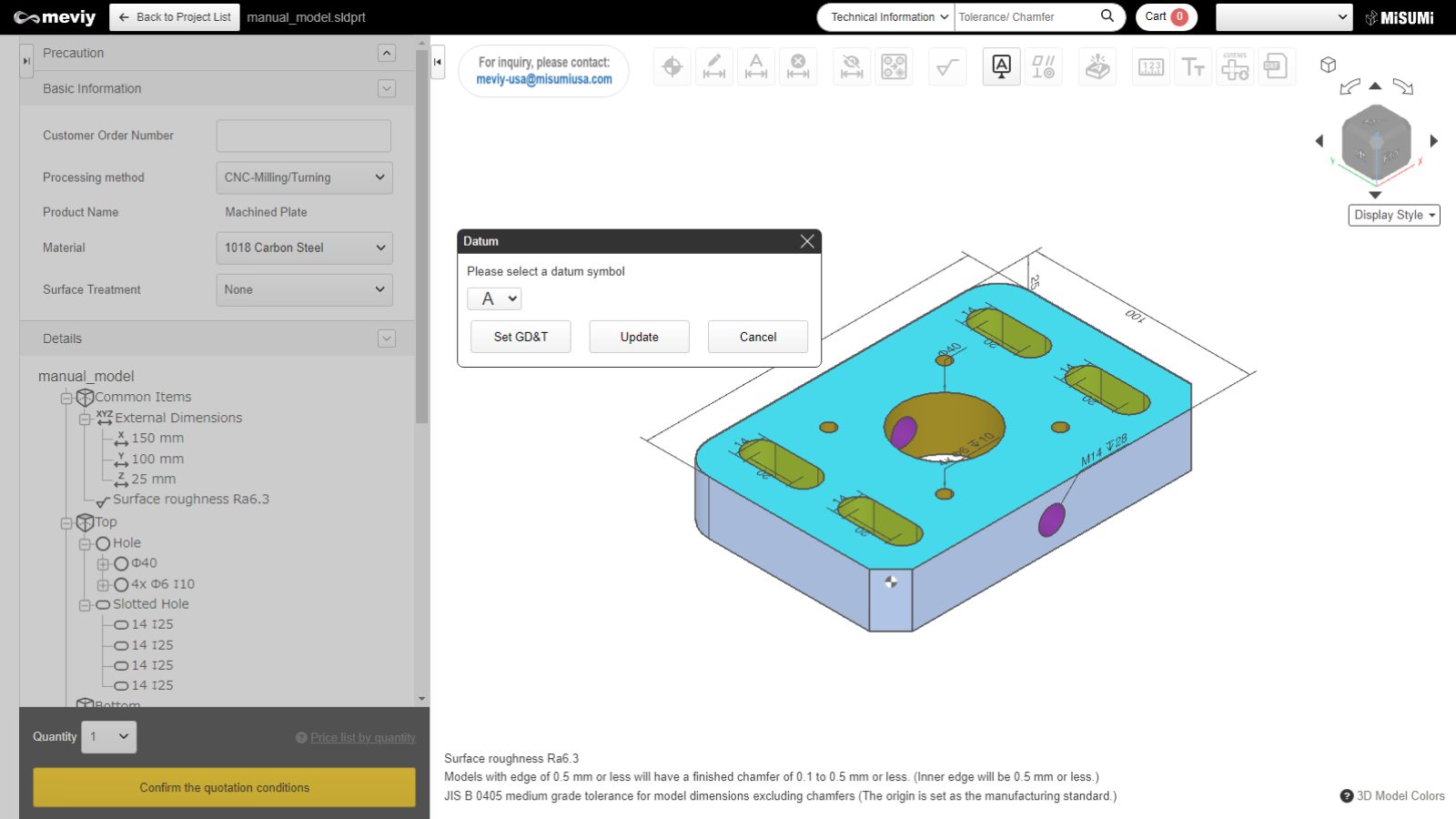
STEP3
Select the datum symbol and click "Update".
Tip
- Click the “Geometric Tolerance Settings” button to proceed to the settings.
- *The settings up to this step will be temporarily saved.
- Reference>>>How to set geometric tolerance STEP2
Caution
- – The following five letters of the alphabet are not displayed.
- I: To be mistaken for the number 1
- O: To be mistaken for the number 0
- Q: To be mistaken for the number 9
- V: To be mistaken for the letter U
- T: To be mistaken for the geometric tolerance ⊥ (squareness)
- N: To be mistaken for the number 2 or the letter Z when it is placed vertically
- Z: To be mistaken for the number 2 or the letter N when it is placed vertically
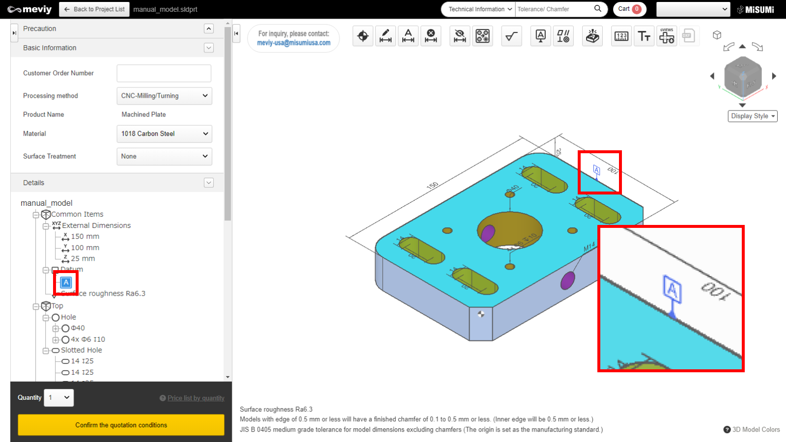
STEP4
Once a datum symbol is set, the datum symbol can be seen on the screen and in the tree view.
How to set geometric tolerances
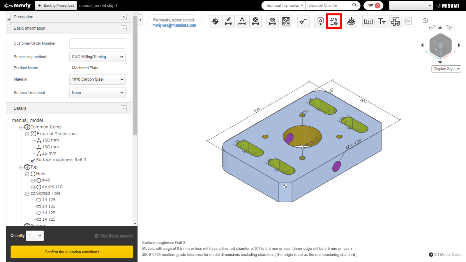
STEP1
Select  from the icons at the top. It can also use the shortcut key (G) to select it.
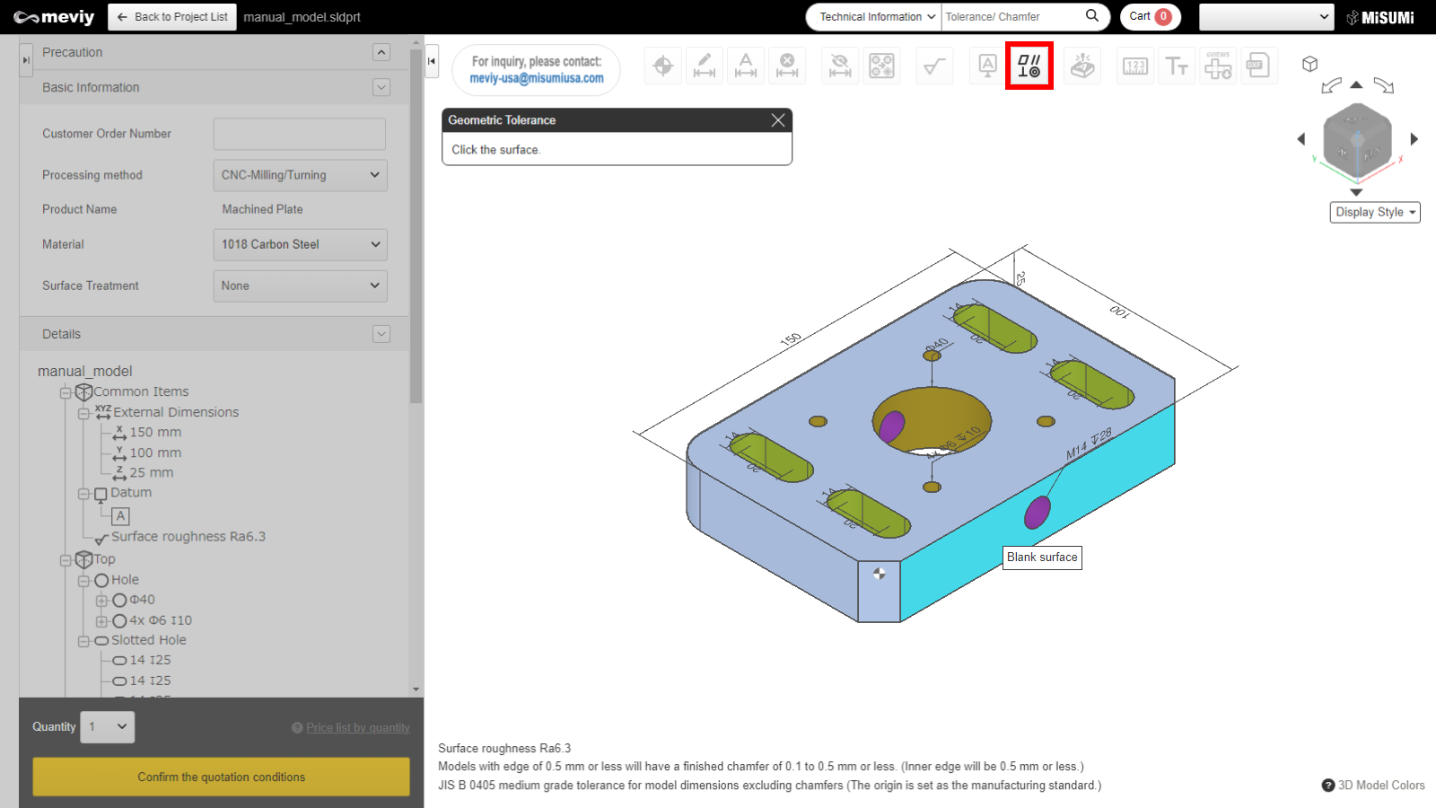
STEP2
Select the surface which needs to be set the geometric tolerances. The target area will be highlighted.
| Long dimension | Short dimension | Thickness | Tolerance lower limit | |
|---|---|---|---|---|
| Automatic Quotation | 10mm or more, 200mm or less | 8mm or more (maximum thickness of each material) | 0.02 | |
| Over 200mm, under 300mm | 0.03 | |||
| Over 300mm, under 400mm | 0.05 | |||
| Manual Quotation | Over 400mm, under 600mm Upper limit: 600mm x 400mm | 5mm or more, less than 8mm | 0.02 | |
Caution
- If the surface is not selectable, the “Not Selectable” icon will be displayed when the mouse hovers over it.

STEP3
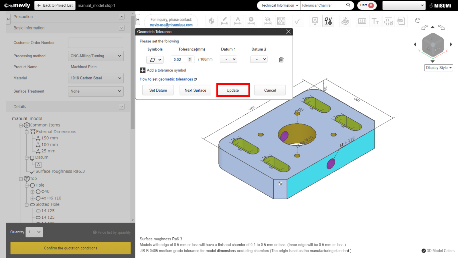
Select a geometric tolerance symbol. The symbol can be chosen from Parallelism, Flatness, or Squareness. When it has completed the selection, click the "Update" button.
Tip
- Even if the datum settings have not been completed, you can specify another datum by clicking the “Datum Settings” button at the bottom left.
- *The settings up to this step will be temporarily saved.
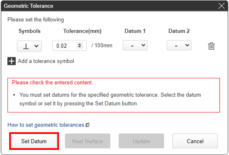
Tolerance values that can be entered are as follows.
| geometric tolerance | Icon | Tolerance range |
|---|---|---|
| Parallelism | 0.02~0.99 | |
| Flatness | 0.02~0.99 | |
| Squareness | 0.02~0.99 |
| Maximum size | Minimum value that can be set | Guaranteed value |
|---|---|---|
| ~100mm | 0.02 mm or less | 0.02 mm or less |
| ~200mm | 0.02 mm or less | 0.04 mm or less |
| ~300mm | 0.03 mm or less | 0.09 mm or less |
| ~400mm | 0.05 mm or less | 0.2 mm or less |
Caution
- A datum is required to specify parallelism and squareness. Please identify them after setting the datum.
- The same geometric tolerance cannot be duplicated on the same surface.
STEP4
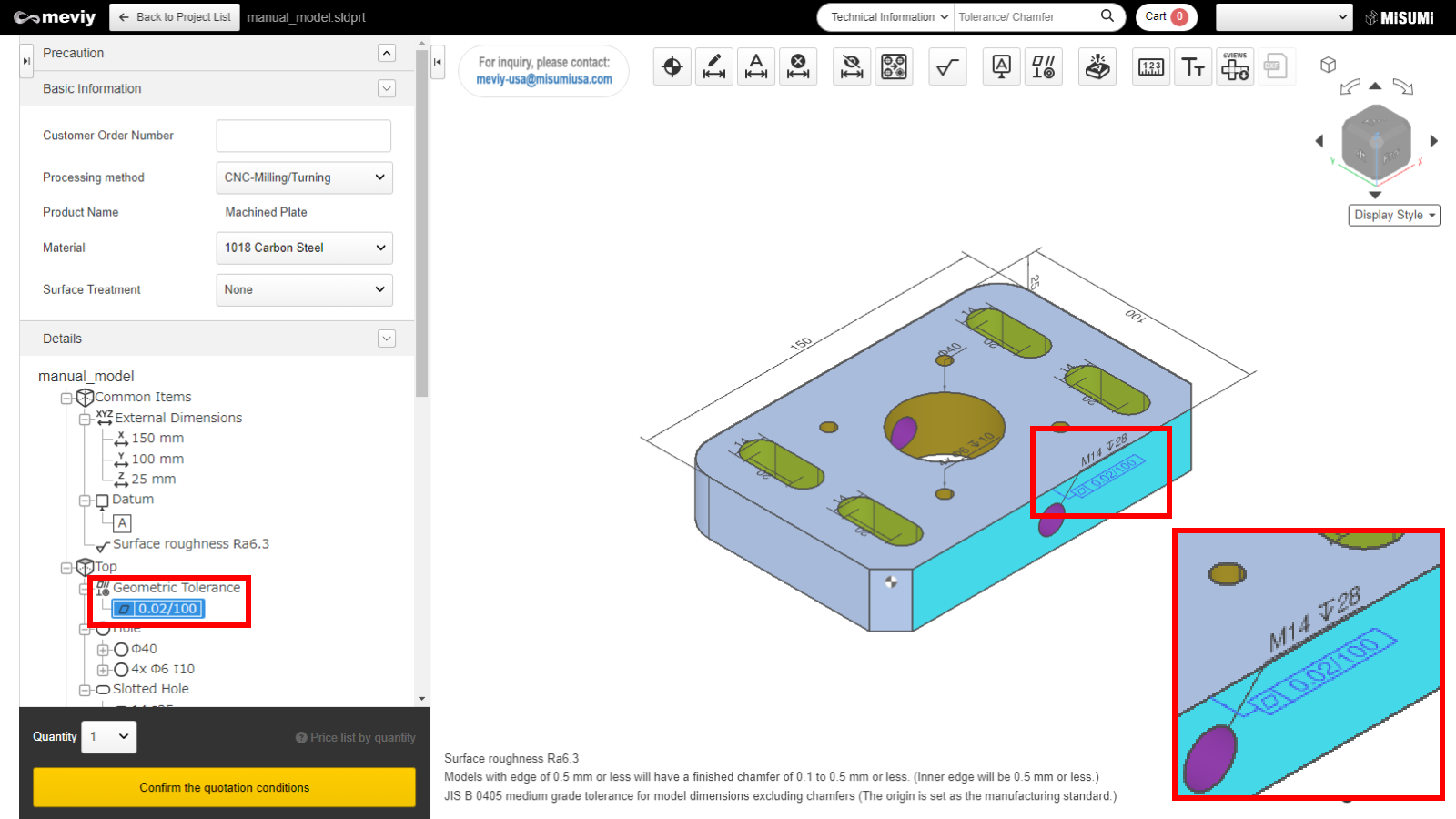
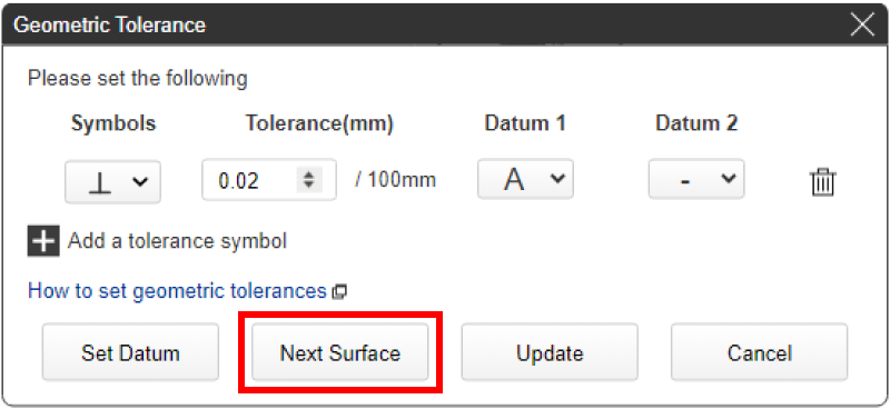
If you need symbols for geometric tolerances and tolerance values, click the "Update" button after completing the selection of datum.
Tip
- If you press the “Select next surface” button without pressing Update, you can set a new geometric tolerance on another surface.
- *The settings up to this step will be temporarily saved.
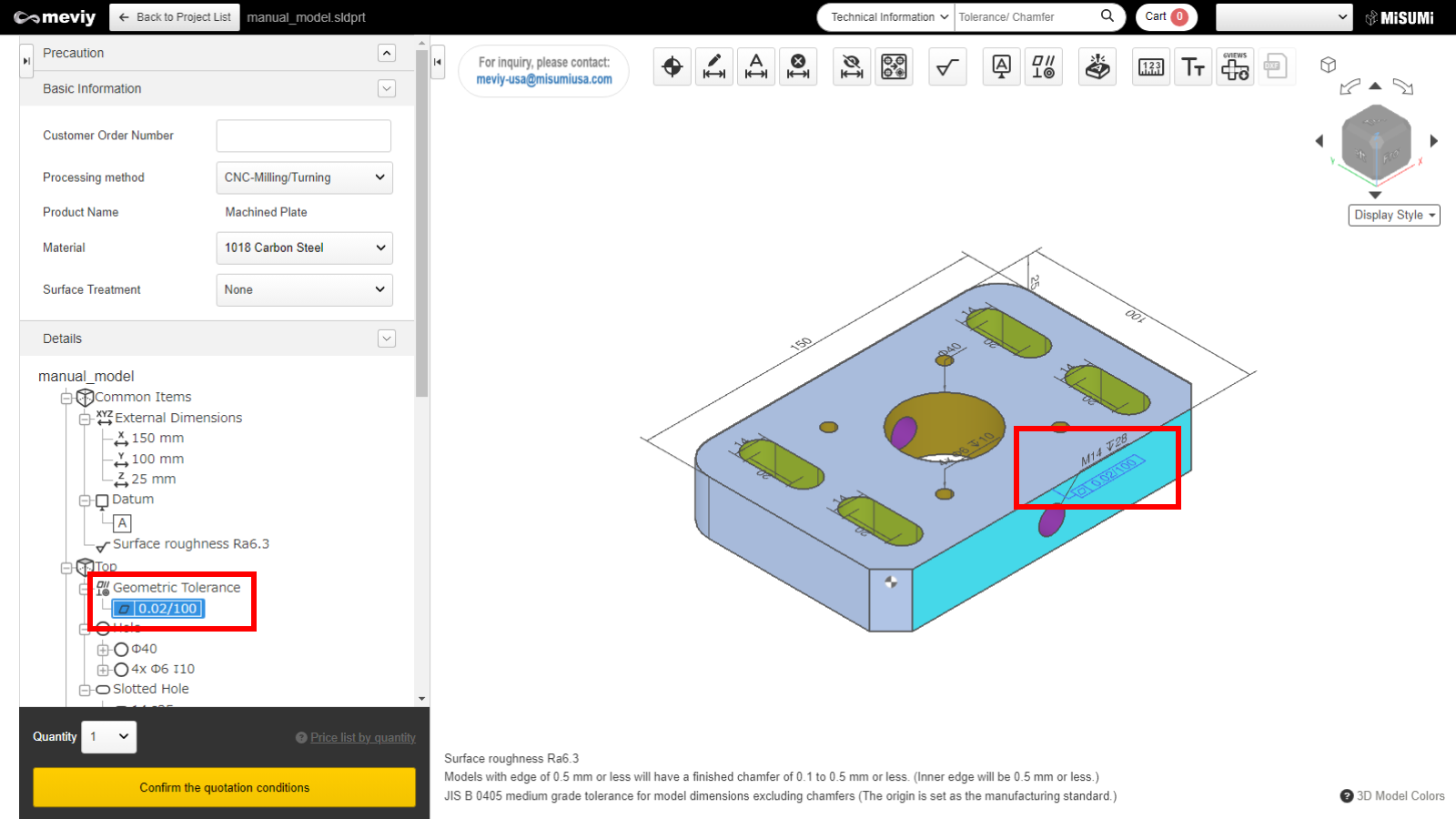
STEP5
After updating the geometric tolerance settings, you can see the geometric tolerance symbol on the screen and tree view.
How to delete datum / geometric tolerances
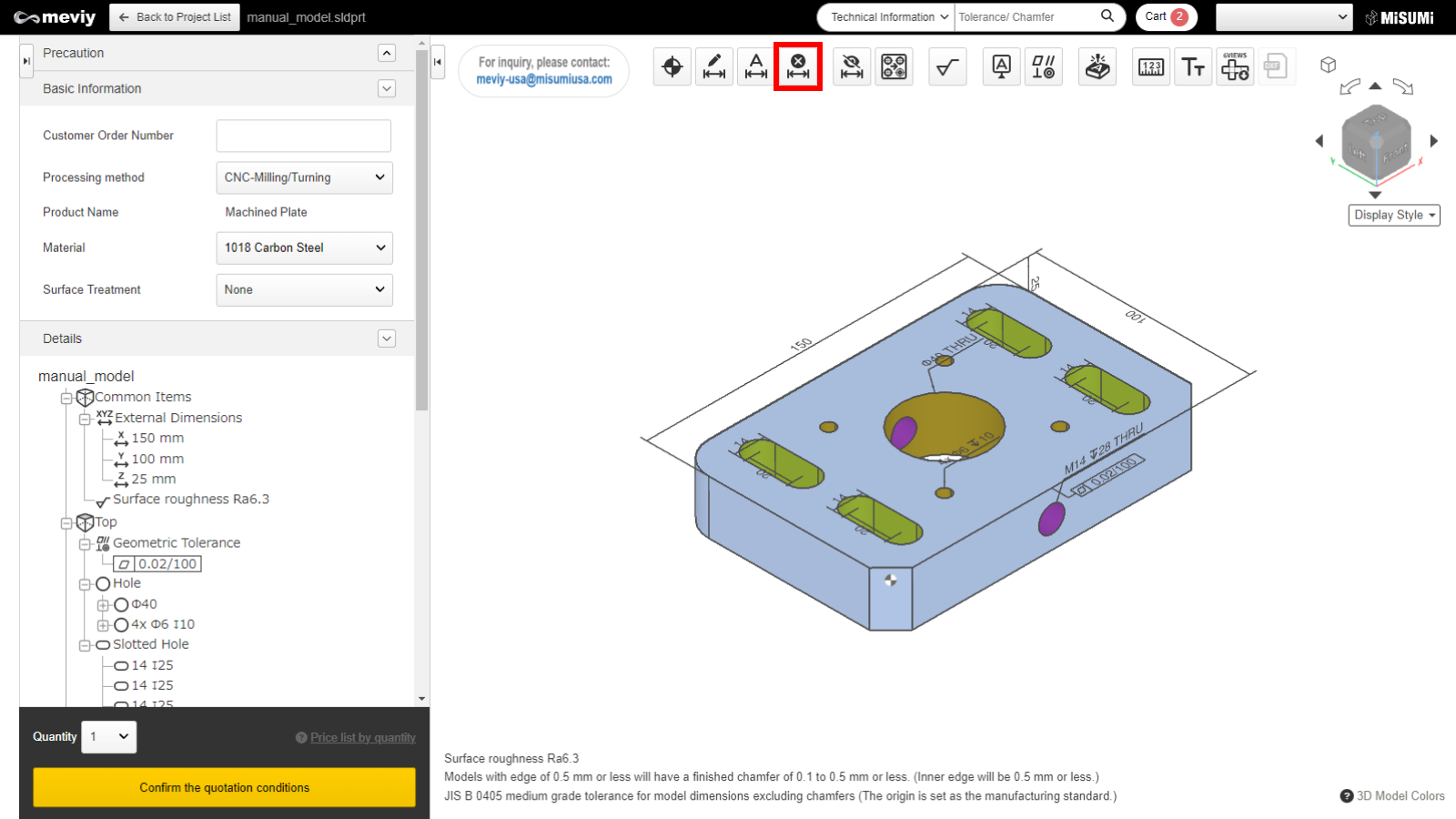
STEP1
Select  from the icons at the top.
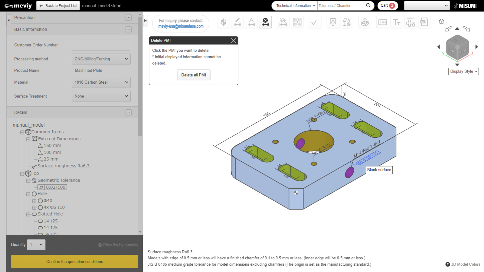
STEP2
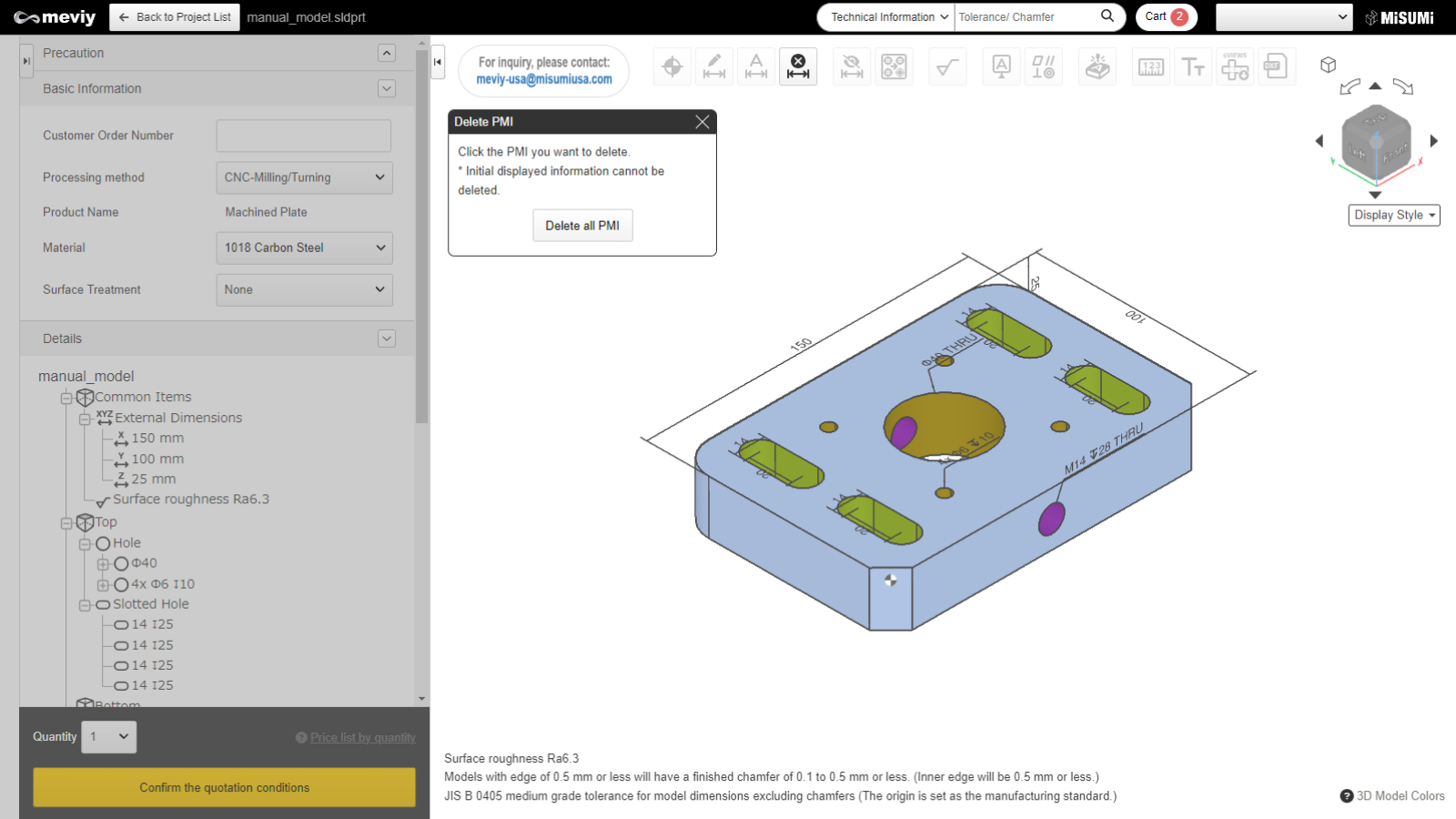
The message "Click the PMI you want to delete" will be displayed. Select the geometric tolerance/datum you want to delete. When you move the cursor over it, the corresponding geometric tolerance/datum will glow blue. It will be deleted when you click it.
Caution
Please note that clicking the “Delete all PMI” button will delete all PMIs you have set.