- HELP
- Technical Information
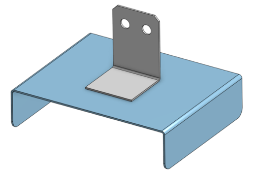
- Welded Sheet Metal
- Design Guidelines
- Determination and Recognizable Size of Weld Locations
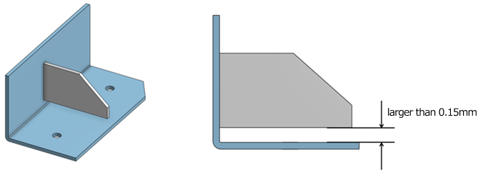
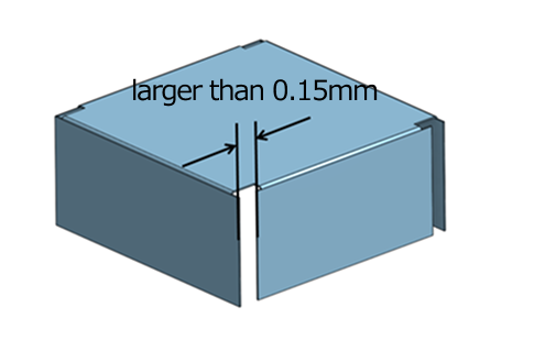
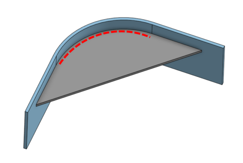
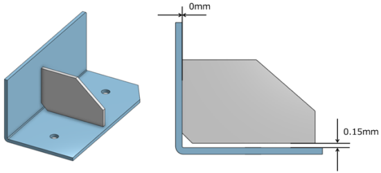
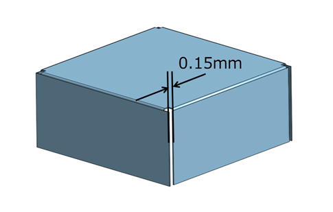
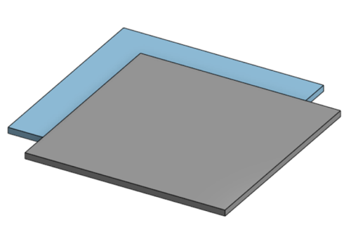
Determination and Recognizable Size of Weld Locations
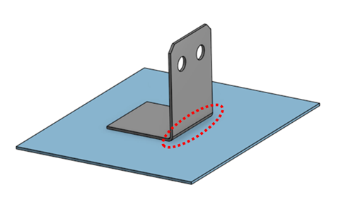
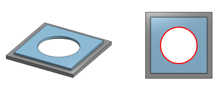
| Models with holes in square members |
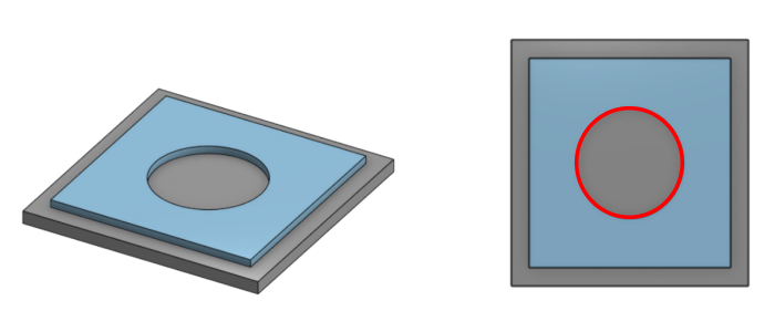 |
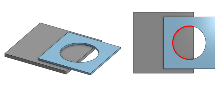 |
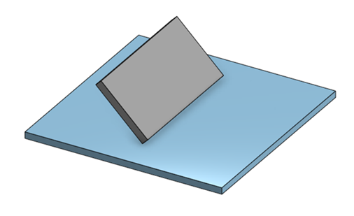
| Models with holes in both members |
 |