- HELP
- Technical Information
- Sheet metal
- Accuracy and Machining Specifications
- Hole Machining Specifications
Hole Machining Specifications
| No. | Nominal Diameter | M3 | M4 | M5 | M6 | M8 | M10 | M12 | M14 | M16 | Example | |
|---|---|---|---|---|---|---|---|---|---|---|---|---|
| 1 | Countersink Diameter (D) | (Min) | 5.54 | 7.53 | 9.43 | 11.34 | 15.24 | 19.22 | 23.12 | 26.52 | 29.01 | 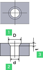 |
| (Max) | 6.72 | 8.96 | 11.20 | 13.44 | 17.92 | 22.40 | 26.88 | 30.80 | 33.60 | |||
| 2 | Pilot Hole Diameter (d) | (Min) | 2.87 | 3.83 | 4.83 | 5.83 | 7.79 | 9.79 | 11.74 | 13.74 | 15.74 | |
| (Max) | 3.30 | 4.40 | 5.50 | 6.60 | 8.54 | 10.62 | 13.50 | 15.50 | 17.50 | |||
| 3 | Countersink Height (t) | Reference Dimensions | 1.86 | 2.48 | 3.10 | 3.72 | 4.96 | 6.20 | 7.44 | 8.40 | 8.80 | |
| No. | Nominal Diameter | #0 | #1 | #2 | #3 | #4 | #5 | #6 | #8 | #10 | #12 | 1/4 | 5/16 | 3/8 | 7/16 | 1/2 | 5/8 | 3/4 | 7/8 | Example | |
|---|---|---|---|---|---|---|---|---|---|---|---|---|---|---|---|---|---|---|---|---|---|
| 1 | Countersink Diameter (D) | (Min) | 0.117 | 0.143 | 0.168 | 0.193 | 0.218 | 0.24 | 0.263 | 0.311 | 0.359 | 0.41 | 0.48 | 0.6 | 0.72 | 0.781 | 0.872 | 1.112 | 1.355 | 1.604 | |
| (Max) | 0.138 | 0.168 | 0.197 | 0.226 | 0.255 | 0.281 | 0.307 | 0.359 | 0.411 | 0.45 | 0.531 | 0.656 | 0.781 | 0.844 | 0.938 | 1.118 | 1.438 | 1.688 | |||
| 2 | Pilot Hole Diameter (d) | (Min) | 0.0568 | 0.0695 | 0.0822 | 0.0949 | 0.1075 | 0.1202 | 0.1329 | 0.1585 | 0.184 | 0.2102 | 0.2435 | 0.3053 | 0.3678 | 0.4294 | 0.4919 | 0.6163 | 0.7406 | 0.8647 | |
| (Max) | 0.06 | 0.073 | 0.086 | 0.099 | 0.112 | 0.125 | 0.138 | 0.164 | 0.19 | 0.2158 | 0.25 | 0.3125 | 0.375 | 0.4375 | 0.5 | 0.625 | 0.75 | 0.875 | |||
| 3 | Countersink Height (t) | Reference Dimensions | 0.045 | 0.055 | 0.064 | 0.073 | 0.082 | 0.09 | 0.097 | 0.112 | 0.127 | 0.135 | 0.162 | 0.198 | 0.234 | 0.234 | 0.252 | 0.284 | 0.396 | 0.468 | |
| No. | Standard Part | Standard Value | Example | ||||
|---|---|---|---|---|---|---|---|
| 1 | Flange thickness | 1/2 of Sheet Thickness (reference value) | 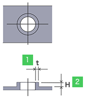 |
||||
| 2 | Flange height | Equal to Sheet Thickness (reference value) | |||||
| No. | Nominal Diameter | M3 | M4 | M5 | M6 | M8 | M10 | M12 | M14 | M16 | Example | |
|---|---|---|---|---|---|---|---|---|---|---|---|---|
| 1 | Countersink Diameter (D) | Standard Dimensions | 6.3 | 8.3 | 10.4 | 12.5 | 16.5 | 20.0 | 24.5 | 28.5 | 32.5 | |
| Maximum | 6.9 | 9.6 | 11.1 | 13.3 | 17.8 | 22.4 | 26.5 | 30.5 | 34.5 | |||
| 2 | Pilot Hole Diameter (d) | Standard Dimensions | 3.4 | 4.3 | 5.3 | 6.5 | 8.5 | 10.5 | 12.5 | 14.5 | 16.5 | |
| Maximum | 4.7 | 7.0 | 8.4 | 9.9 | 13.8 | 14.2 | 14.5 | 16.5 | 18.5 | |||
| 3 | Countersink Height (t) | Reference Dimensions | 1.5~1.6 | 2.0~2.3 | 2.5~2.7 | 2.2~2.9 | 3.2~3.8 | 4.9~5.1 | 6.0 | 7.0 | 8.0 | |
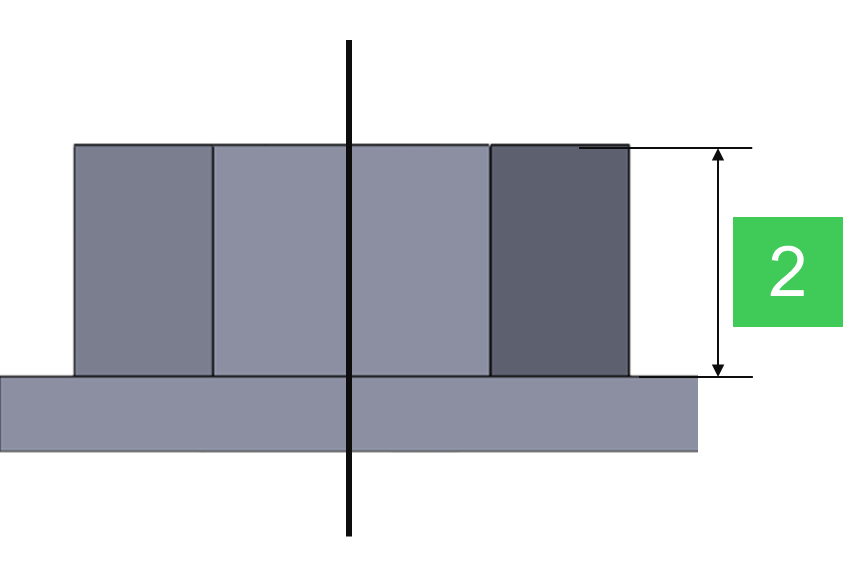
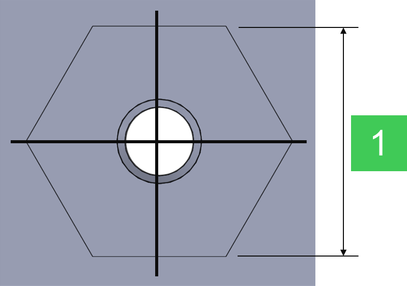
| No. | Nominal diameter | M3 | M4 | M5 | M6 | M8 | M10 | M12 | Example |
|---|---|---|---|---|---|---|---|---|---|
| 1 | Width of two face | 5.5 | 7.0 | 8.0 | 10.0 | 13.0 | 15.0 | 17.0 |
|
| 2 | Hight of nut | 2.1 | 2.3 | 3.1 | 4.1 | 4.6 | 6.1 | 7.1 |

| No. | Nominal diameter | M4 | M5 | M6 | M8 | M10 | M12 | Example |
|---|---|---|---|---|---|---|---|---|
| 1 | Width of two face | 11.0 | 11.0 | 13.0 | 15.0 | 17.0 | 19.0 |
|
| 2 | Hight of nut | 4.2 | 4.2 | 5.2 | 6.7 | 8.2 | 9.8 |