- HELP
- Technical Information
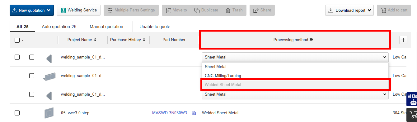
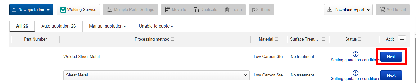
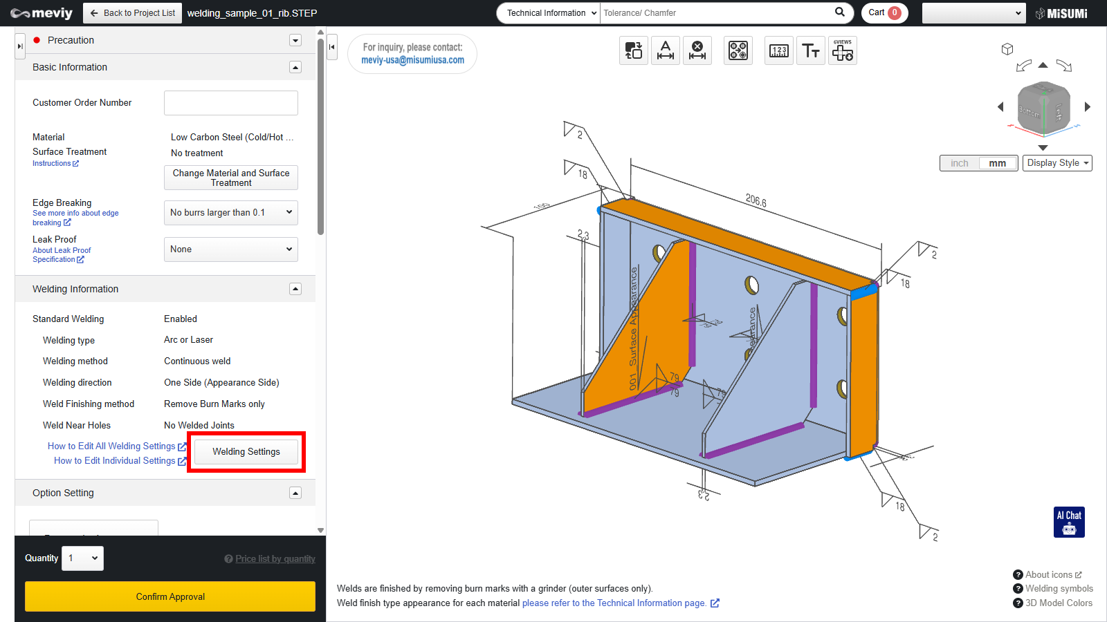
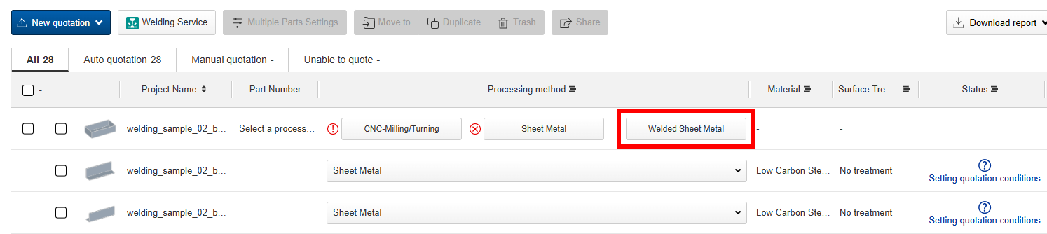
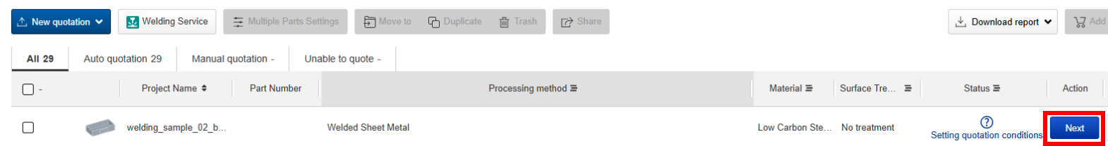
- Welded Sheet Metal
- Design Guidelines
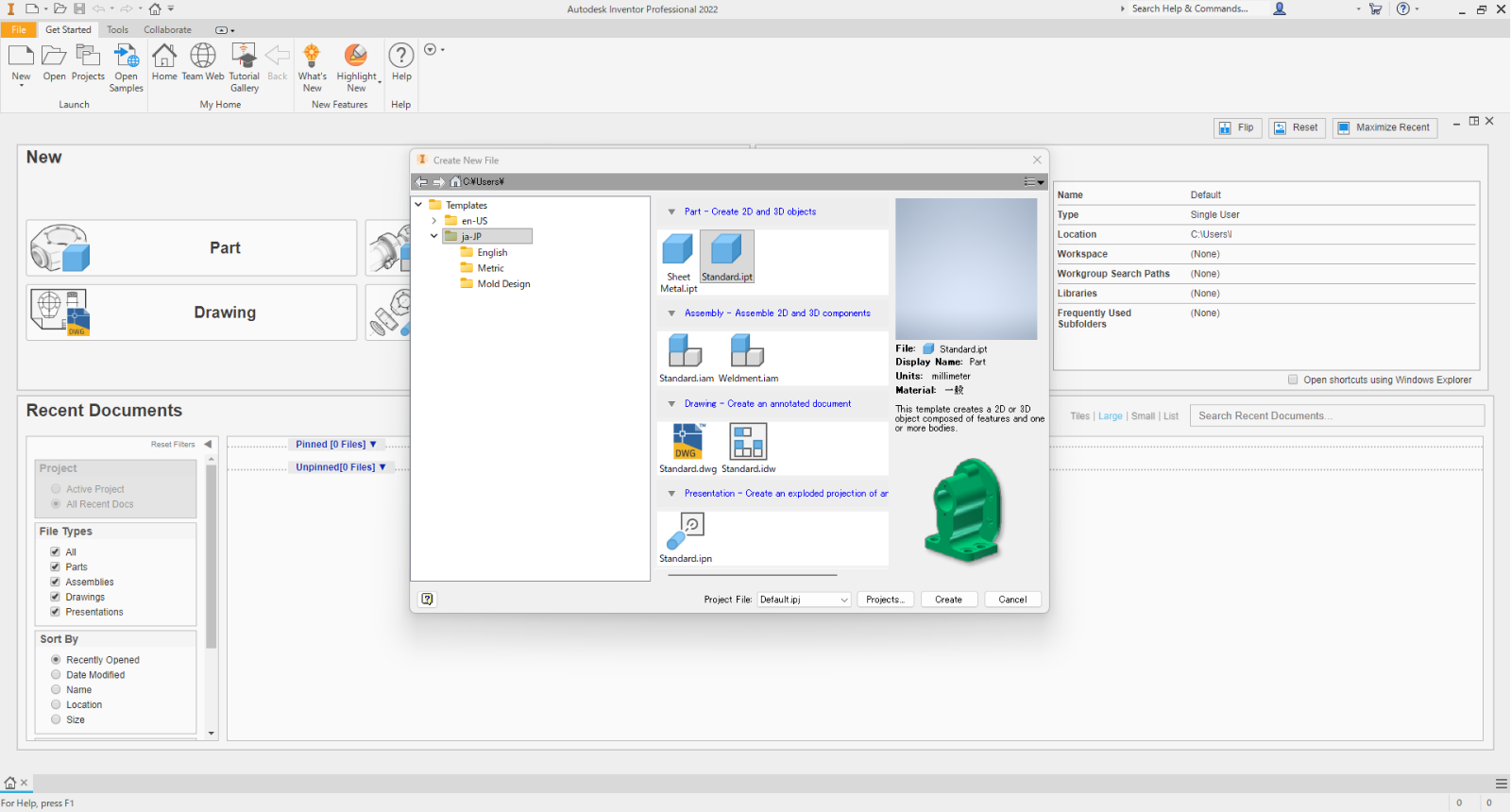
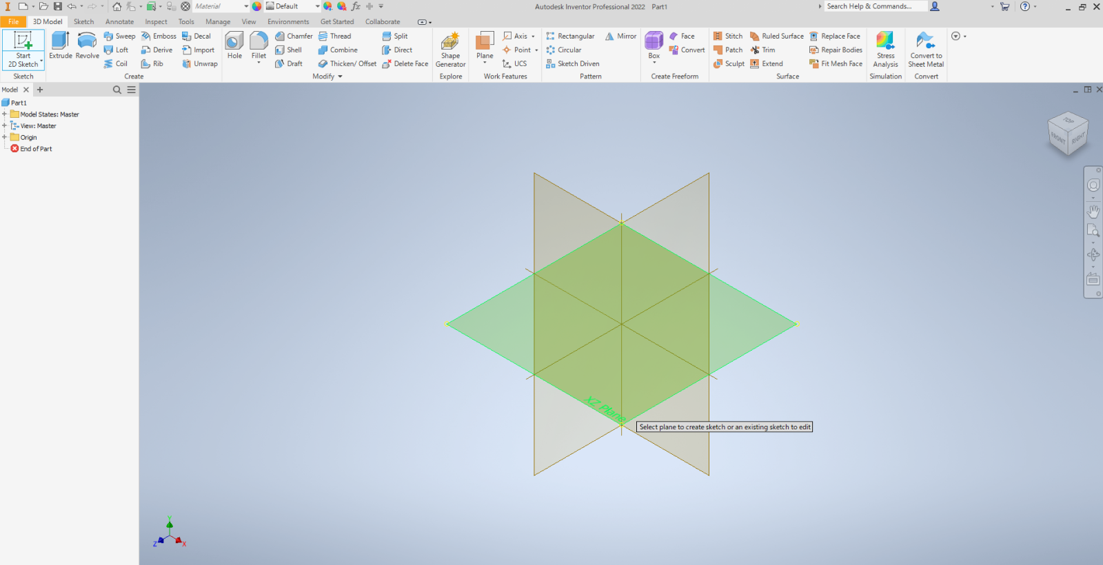
- 3D Design Guide for Welded Sheet Metal parts
3D Design Guide for Welded Sheet Metal parts
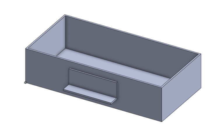
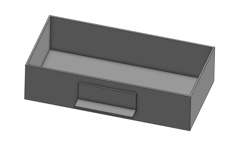
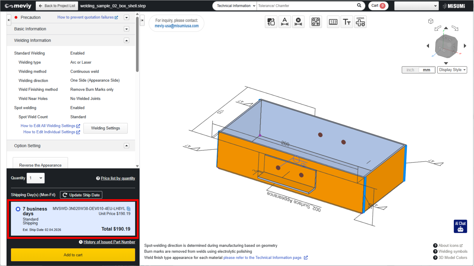
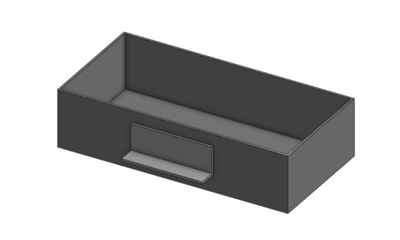
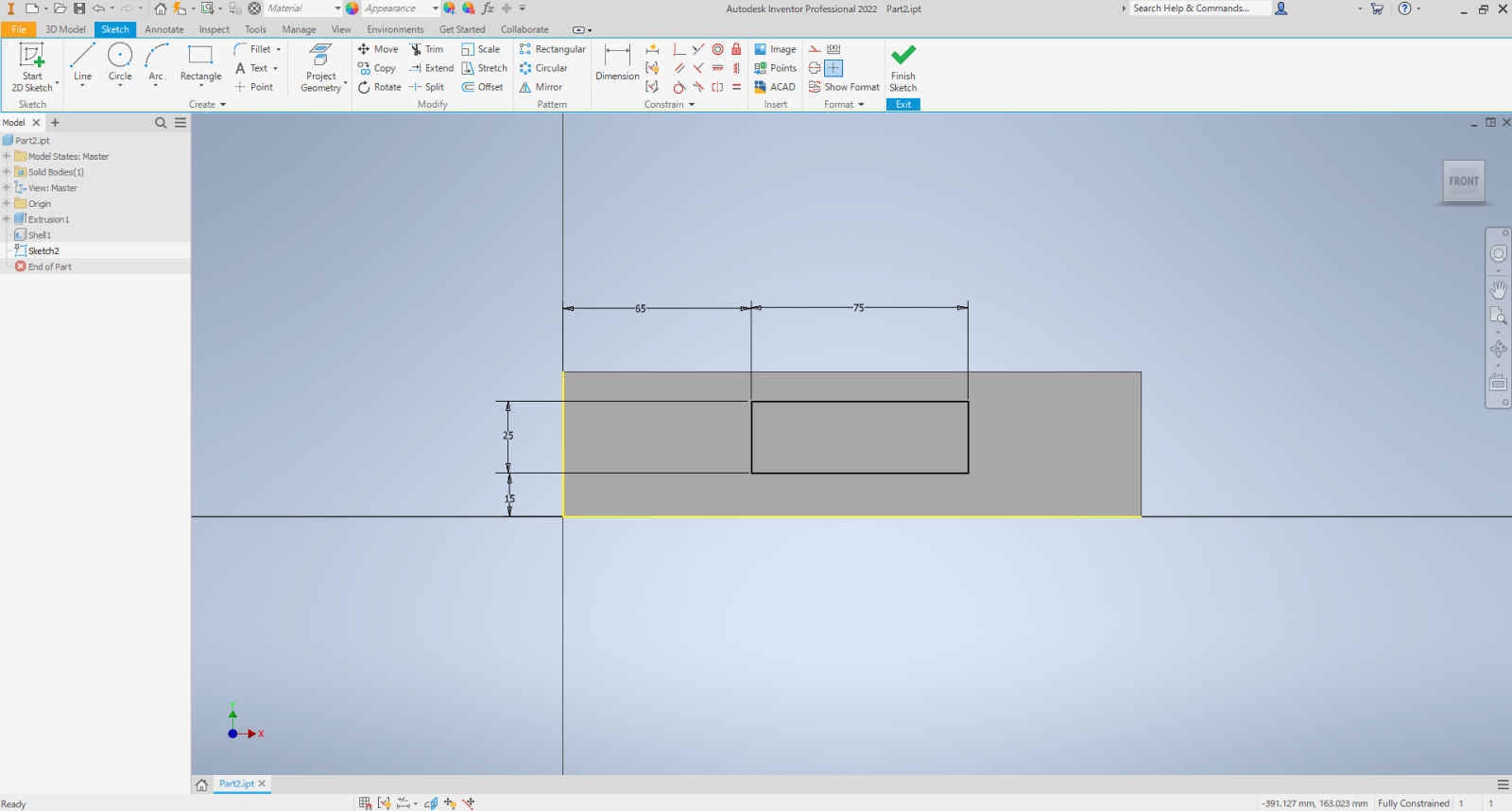
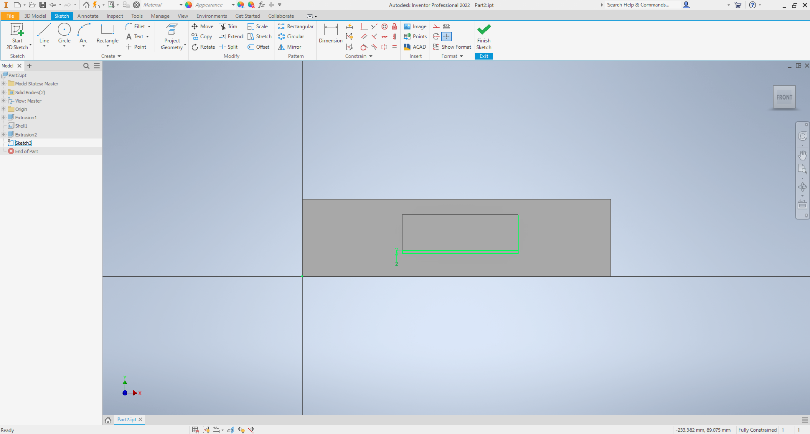
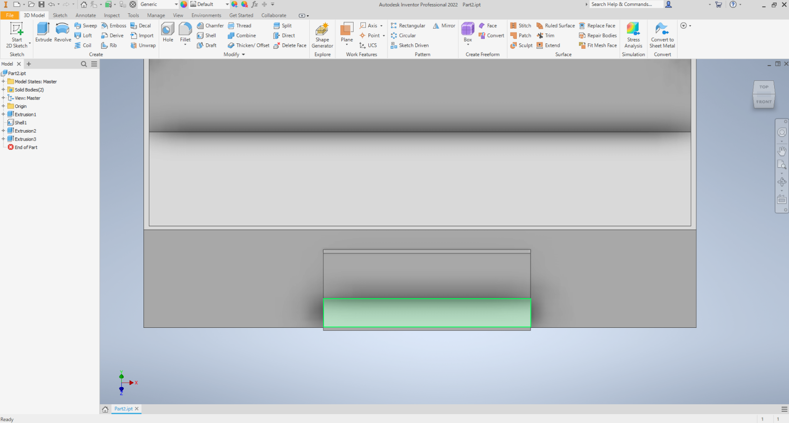
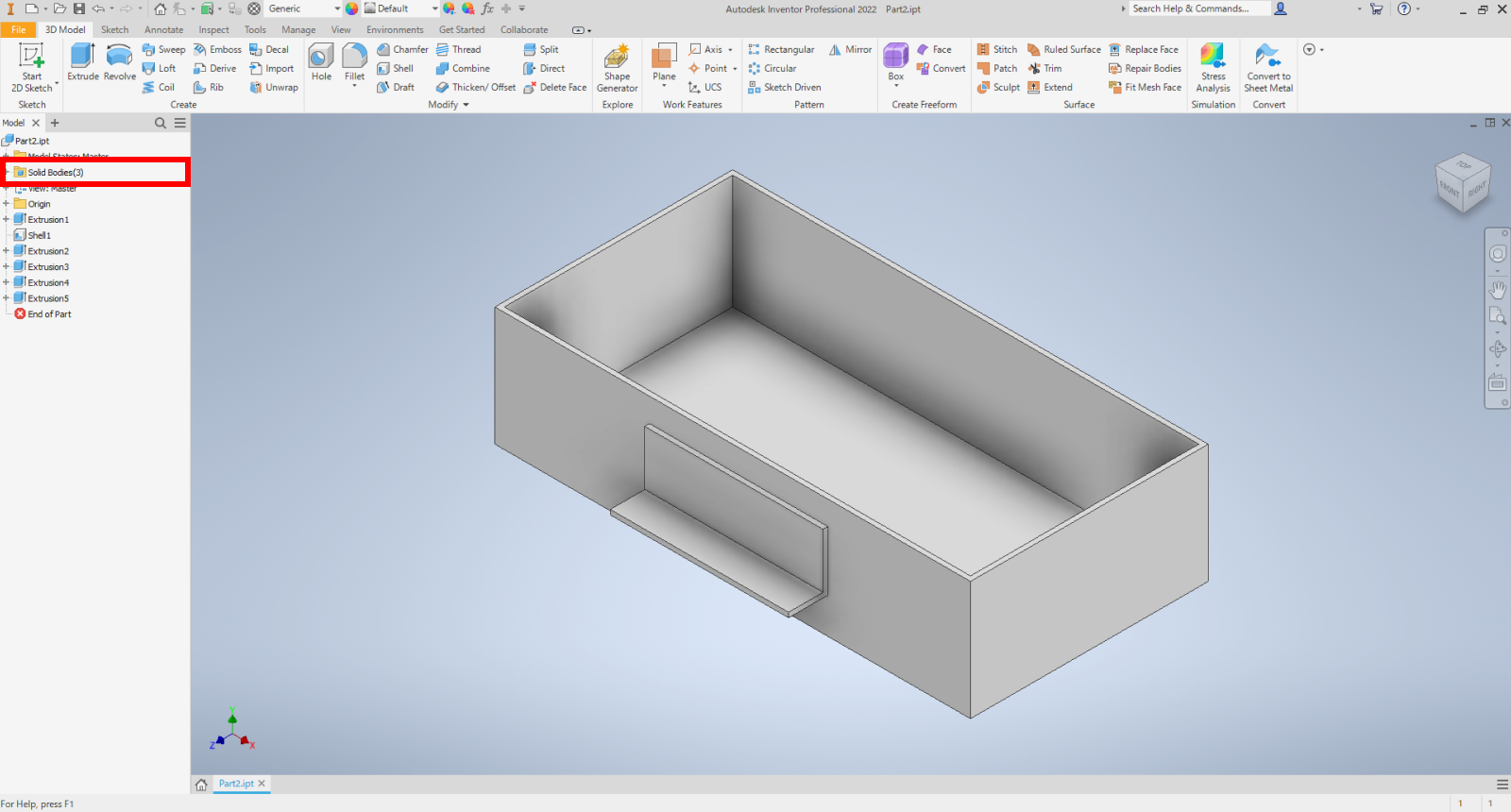
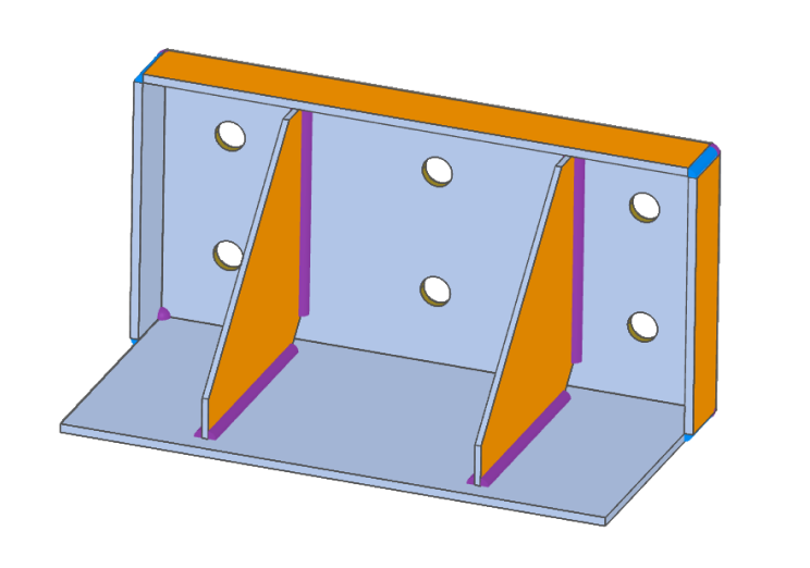
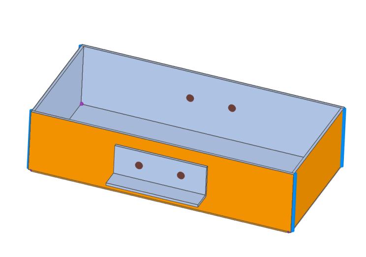
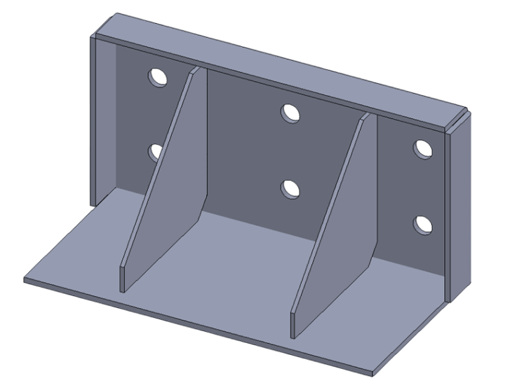
| Example 1: Rib Shape | Example 2: Box Shape |
 |
 |
| File Download » Here | |
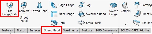
Tip
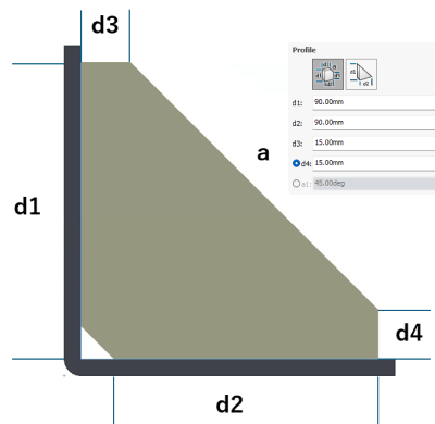
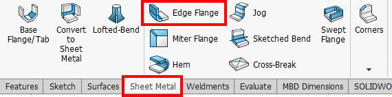
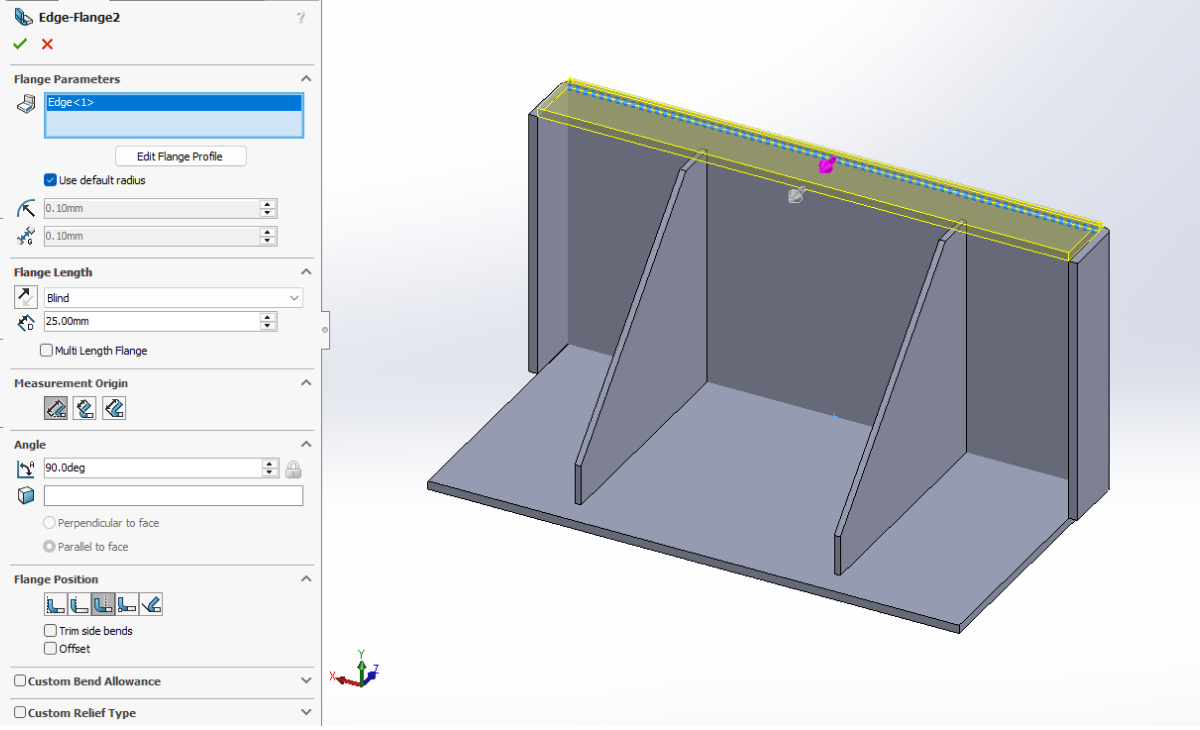
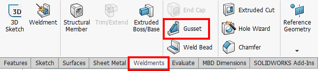
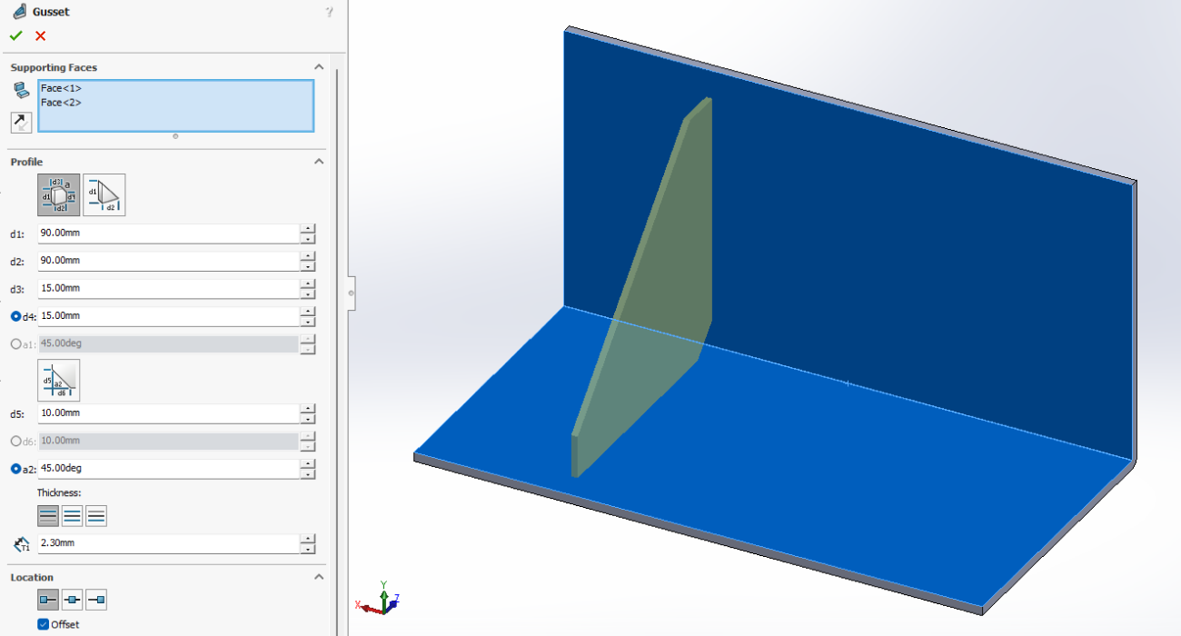
- SOLIDWORKS Weld Rib Feature
- This allows you to create ribs more quickly and simply than by creating a sketch and using the Extrude Boss feature.
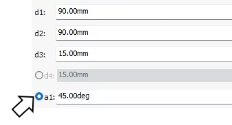
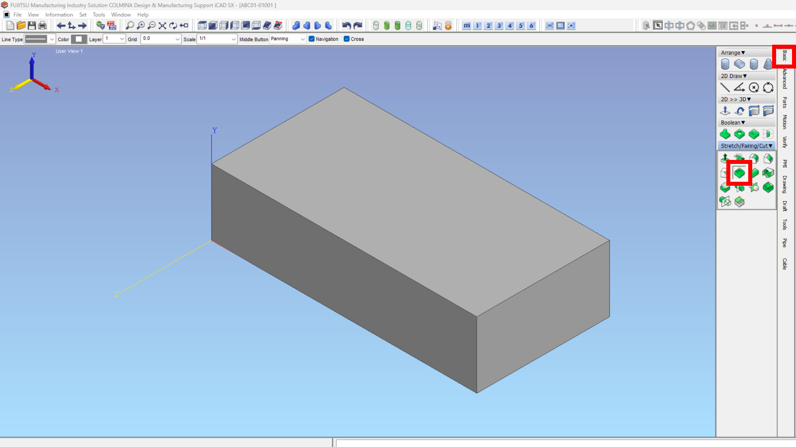
- Select the face to create and enter the outline size. d4 and a1 become editable when toggled via radio buttons.
-