- HELP
- Technical Information
- CNC Turning
- Accuracy and Machining Specifications
- Default General Tolerance Standards
Default General Tolerance Standards
- CNC Milling service does not display dimensions or tolerances other than diameter information and length when 3D CAD data is uploaded, assuming that the customer specifies their desired tolerances.
Default General Tolerance Standards for Machined Dimensions
(Standard products conform to JIS B 0405:1991/JIS B 0419:1991, International Economy products conform to the standards of the country of manufacture.)
- The following standards are applied to the datum according to machining standards.
- The datum can be positioned at any location.
- *International Economy is not available for CNC Turning products.
Length, Excluding Chamfer, Dimensional Tolerances
[mm]
| Product lineup | Tolerance Grade | Base Dimensions | ||||||
|---|---|---|---|---|---|---|---|---|
| Symbol | Description | ≥0.5 ≤3 | >3 ≤6 | >6 ≤30 | >30 ≤120 | >120 ≤400 | >400 ≤1000 | |
| Standard | m | Medium | ±0.1 | ±0.1 | ±0.2 | ±0.3 | ±0.5 | ±0.8 |
Tolerances for Chamfer Length Dimensions (Corner Radius and Corner Chamfer Dimensions)
[mm]
| Product lineup | Tolerance Grade | Base Dimensions | |||
|---|---|---|---|---|---|
| Symbol | Description | ≥0.5 ≤3 | >3 ≤6 | >6 | |
| Standard | C | Coarse | ±0.4 | ±1 | ±2 |
Angle Dimensional Tolerances
| Product lineup | Tolerance Grade | Length of the Shorter Angle Edge | |||||
|---|---|---|---|---|---|---|---|
| Symbol | Description | ≤10 | >10 ≤50 | >50 ≤120 | >120 ≤400 | >400 | |
| Standard | m | Medium | ±1° | ±30’ | ±20’ | ±10’ | ±5’ |
General Tolerances of Perpendicularity
[mm]
| Product lineup | Tolerance Grade | Nominal Length of the Shorter Edge | |||
|---|---|---|---|---|---|
| Symbol | ≤100 | >100 ≤300 | >300 ≤1000 | >1000 ≤5000 | |
| Standard | K | 0.4 | 0.6 | 0.8 | 1 |
Geometric Tolerance Standards for Lathe Machining
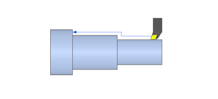
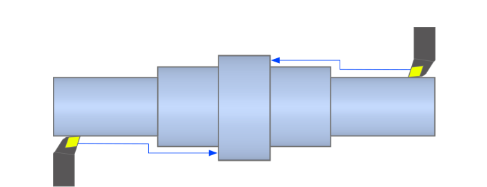
The following tolerance values are also guaranteed for Hardening. However, this may not apply to certain product shapes such as thin-walled products, long products, and products with a high material removal rate.
[mm]
| Geometric Tolerance Completed on One Side with Maximum Diameter as the Origin | Geometric Tolerance for Both Sides with Maximum Diameter as the Origin | |||||
|---|---|---|---|---|---|---|
| Outer Diameter | Inner Diameter | Outer Diameter | Inner Diameter | L (Length) | Standard | |
| K (Geometric Tolerance Value) | ||||||
| Perpendicularity | 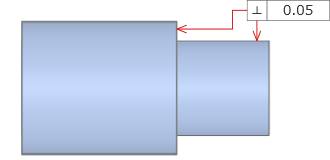 | 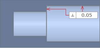 | 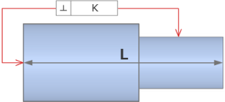 | 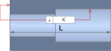 | L ≦ 100 | 0.06 |
| 100 < L ≦ 300 | 0.1 | |||||
| 300 < L ≦ 500 | 0.15 | |||||
| L < 500 | 0.2 | |||||
| Concentricity | 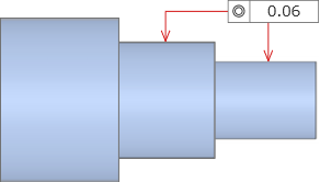 | 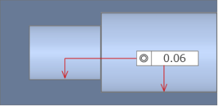 | 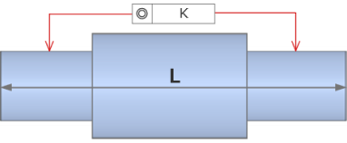 | 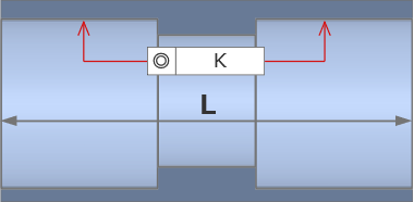 | L ≦ 100 | 0.1 |
| 100 < L ≦ 300 | 0.2 | |||||
| 300 < L ≦ 500 | 0.3 | |||||
| L < 500 | 0.5 | |||||
| Parallelism | 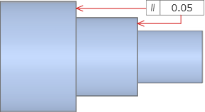 | 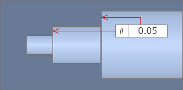 | 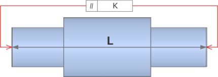 | 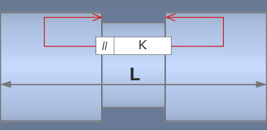 | L ≦ 100 | 0.06 |
| 100 < L ≦ 300 | 0.1 | |||||
| 300 < L ≦ 500 | 0.15 | |||||
| L < 500 | 0.2 | |||||
| Circularity | 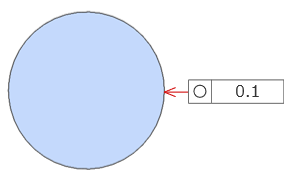 | 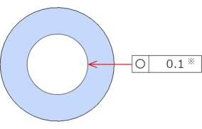 | ||||
- *Circularity should be equal to the dimensional tolerance value for the diameter, but it must not exceed the specified tolerance value of circular runout in the radial direction.
- e.g.1 : ø100 without tolerance = Circularity 0.1 mm
- e.g.2 : ø100 with ±0.02 mm tolerance = Circularity 0.04 mm
Tip
Reasons for disparities in precision between one side and both sides
|
|
 |
 |
[mm]
| Product lineup | Tolerance Grade | Nominal Length | ||||
|---|---|---|---|---|---|---|
| Symbol | ≤10 | >10 ≤30 | >30 ≤100 | >100 ≤300 | >300 ≤1000 | |
| Standard | K | 0.05 | 0.1 | 0.2 | 0.4 | 0.6 |
Surface Roughness
- The surface roughness is √Ra6.3 (√Rz25).
- The surface roughness is displayed in the lower left corner of the 3D viewer, and the roughness symbol can be customized in the user settings.
- You can select √Ra6.3/3.2 for surface roughness in User Settings > Initial Quotation Conditions.
Tip
As shown in the figure below, you can select the value for surface roughness from √Ra6.3/3.2 in the tree view. You can also change the default values in Initial Quotation Conditions in User Settings.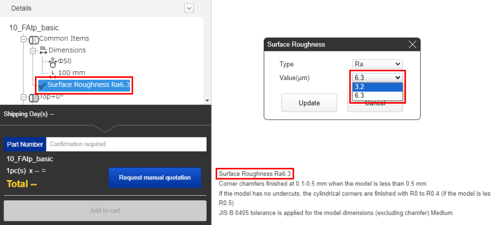
External Corners, Cylinder Internal Corners, Chamfered Edge
- Models with external corners of less than C/R0.5 will have C/R 0.1 to 0.4 mm or edge breaking.
- If the internal corners of the cylinder are smaller than 0.5, the tool edge will leave a finish of R0.4 mm.
Caution
Specification of “no chamfering” is not supported.